
Related Manuals for Atmel AT91SAM7A3-EK


Summary of Contents for Atmel AT91SAM7A3-EK
- Page 1 AT91SAM7A3-EK Evaluation Board ....................User Guide...
-
Page 2: Table Of Contents
Table of Contents Section 1 Overview....................1-1 Scope......................1-1 Deliverables ....................1-1 The AT91SAM7A3-EK Evaluation Board..........1-1 Section 2 Setting Up the AT91SAM7A3-EK Evaluation Board......2-1 Electrostatic Warning ................2-1 Requirements....................2-1 Layout .......................2-2 Powering Up the Board ................2-3 Backup Power Supply ................2-3 Getting Started..................2-3 AT91SAM7A3-EK Block Diagram .............2-4... -
Page 3: Overview
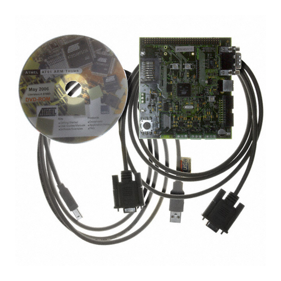
Scope The AT91SAM7A3-EK evaluation kit enables evaluation capabilities and code develop- ment of applications running on an AT91SAM7A3. This guide focuses on the AT91SAM7A3-EK board as an evaluation platform. Deliverables The AT91SAM7A3-EK package contains the following items: ! an AT91SAM7A3-EK board... - Page 4 Overview AT91SAM7A3-EK Evaluation Board User Guide 6165C–ATARM–26-Jun-06...
-
Page 5: Setting Up The At91Sam7A3-Ek Evaluation Board
Avoid touching the component pins or any other metallic element. Requirements In order to set up the AT91SAM7A3-EK evaluation board, the following items are required: ! the AT91SAM7A3-EK evaluation board itself ! an A/B-type USB cable ! a DC USB power adapter (5V at 0.5 A) with USB A/B cable... -
Page 6: Layout
Setting Up the AT91SAM7A3-EK Evaluation Board Layout Figure 2-1. Top Level Layout AT91SAM7A3-EK Evaluation Board User Guide 6165C–ATARM–26-Jun-06... -
Page 7: Powering Up The Board
The AT91SAM7A3-EK evaluation board is delivered with a DVD-ROM containing all necessary information and step-by-step procedures for working with the most common development tool chains. Please refer to this DVD-ROM, or to the Atmel web site, http://www.atmel.com/products/AT91/, for the most up-to-date information on getting started with the AT91SAM7A3-EK. -
Page 8: At91Sam7A3-Ek Block Diagram
Setting Up the AT91SAM7A3-EK Evaluation Board AT91SAM7A3-EK Block Diagram Figure 2-2. Block Diagram SD/MMC DBGU USB DEVICE DATAFLASH (NPCS03) RS232 CARD READER VBUS VBUS ATA6661 ADM3202A MN18 3.3V 4 3 2 1 9 TJA1050 TJA1050 nSHUTDOWN NRST YELLOW YELLOW POWER LED... -
Page 9: Board Description
– Power Optimization Capabilities, including Slow Clock Mode (Down to 500 Hz), Idle Mode, Standby Mode and Backup Mode – Four Programmable External Clock Signals ! Advanced Interrupt Controller (AIC) – Individually Maskable, Eight-level Priority, Vectored Interrupt Sources AT91SAM7A3-EK Evaluation Board User Guide 6165C–ATARM–26-Jun-06... - Page 10 – 8- to 16-bit Programmable Data Length, Four External Peripheral Chip Selects ! Three 3-channel 16-bit Timer/Counters (TC) – Three External Clock Inputs, Two Multi-purpose I/O Pins per Channel – Double PWM Generation, Capture/Waveform Mode, Up/Down Capability AT91SAM7A3-EK Evaluation Board User Guide 6165C–ATARM–26-Jun-06...
- Page 11 – I²S Analog Interface Support, Time Division Multiplex Support – High-speed Continuous Data Stream Capabilities with 32-bit Data Transfer ! One Two-wire Interface (TWI) – Master Mode Support Only, All Two-wire Atmel EEPROMs Supported ! Multimedia Card Interface (MCI) – Compliant with Multimedia Cards and SD Cards –...
-
Page 12: At91Sam7A3 Block Diagram
ADC0_AD3 TIOA4 ADC0_AD4 TIOB4 ADC0 ADC0_AD5 ADC0_AD6 TIOA5 ADC0_AD7 TIOB5 ADC0_ADTRG TCLK6 ADVREFP Timer Counter TCLK7 VDDANA TCLK8 TIOA6 ADC1_AD0 ADC1_AD1 TIOB6 ADC1_AD2 ADC1 TIOA7 ADC1_AD3 ADC1_AD4 TIOB7 ADC1_AD5 ADC1_AD6 TIOA8 ADC1_AD7 TIOB8 ADC1_ADTRG AT91SAM7A3-EK Evaluation Board User Guide 6165C–ATARM–26-Jun-06... -
Page 13: Memory
! Two analog up to Vref inputs. One external user input and one back-looped with buffered PWM0 output. ! One buffered PWM0 analog output (up to Vref) 3.10 User Interface ! One 5-way joystick (4 directions and push for confirmation) ! Four general-purpose buffered green LEDs (PWM controlled) AT91SAM7A3-EK Evaluation Board User Guide 6165C–ATARM–26-Jun-06... -
Page 14: Debug Interface
! All I/Os of the AT91SAM7A3 are routed to peripheral extension connectors (J9). This allows the developer to check the integrity of the components and to extend the features of the board by adding external hardware components or boards. AT91SAM7A3-EK Evaluation Board User Guide 6165C–ATARM–26-Jun-06... -
Page 15: Configuration Straps
J22 should not be closed at the same time. Opened Do not use: Factory test mode Opened Select ICE mode or JTAG mode (Closed) Opened External XIN clock input. S8 and S9 must be open. AT91SAM7A3-EK Evaluation Board User Guide 6165C–ATARM–26-Jun-06... - Page 16 Enables the use of the User LED DS4 (PA25) Closed Enables the use of the User LED DS3 (PA24) Closed Enables the use of the User LED DS2 (PA21) Closed Enables the use of the User LED DS1 (PA20) AT91SAM7A3-EK Evaluation Board User Guide 6165C–ATARM–26-Jun-06...
- Page 17 GND Test point GND_ADC Test point Note: 1. These jumpers are provided for measuring power consumption. By default, they are closed. To use this feature, the user has to open the strap and insert an anmeter. AT91SAM7A3-EK Evaluation Board User Guide 6165C–ATARM–26-Jun-06...
- Page 18 Configuration Straps AT91SAM7A3-EK Evaluation Board User Guide 6165C–ATARM–26-Jun-06...
-
Page 19: Schematics
Section 5 Schematics Schematics This section contains the following schematics: ! Processor ! I/O AT91SAM7A3-EK Evaluation Board User Guide 6165C–ATARM–26-Jun-06... - Page 20 DES. DATE DATE DATE VER. VER. VER. DATE DATE DATE 74ALVC04 74ALVC04 74ALVC04 74ALVC04 WRITE PROTECT NRST AT91SAM7A3-EK AT91SAM7A3-EK AT91SAM7A3-EK SCALE SCALE SCALE REV. REV. REV. SHEET SHEET SHEET NORMALLY OPEN PROCESSOR BOARD PROCESSOR BOARD PROCESSOR BOARD This agreement is our property. Reproduction and publication without our written authorization shall expose offender to legal proceedings.
- Page 21 DES. DES. DES. DATE DATE DATE VER. VER. VER. DATE DATE DATE AT91SAM7A3-EK AT91SAM7A3-EK AT91SAM7A3-EK SCALE SCALE SCALE REV. REV. REV. SHEET SHEET SHEET This agreement is our property. Reproduction and publication without our written authorization shall expose offender to legal proceedings.
- Page 22 Schematics AT91SAM7A3-EK Evaluation Board User Guide 6165C–ATARM–26-Jun-06...
-
Page 23: Revision History
Added information on SAM-BA in Section 2.6. 05-415 6165C Removed references to 32 Mbit serial DataFlash (AT45DB321C-CNC) in Section 1.3 2846 and in Section 3.3. Inserted new Figure 2-2 and new schematics in Section AT91SAM7A3-EK Evaluation Board User Guide 6165C–ATARM–26-Jun-06... - Page 24 Revision History AT91SAM7A3-EK Evaluation Board User Guide 6165C–ATARM–26-Jun-06...
- Page 25 Disclaimer: The information in this document is provided in connection with Atmel products. No license, express or implied, by estoppel or otherwise, to any intellectual property right is granted by this document or in connection with the sale of Atmel products. EXCEPT AS SET FORTH IN ATMEL’S TERMS AND CONDI- TIONS OF SALE LOCATED ON ATMEL’S WEB SITE, ATMEL ASSUMES NO LIABILITY WHATSOEVER AND DISCLAIMS ANY EXPRESS, IMPLIED OR STATUTORY...
- Page 26 Mouser Electronics Authorized Distributor Click to View Pricing, Inventory, Delivery & Lifecycle Information: Atmel AT91SAM7A3-EK...
Need help?
Do you have a question about the AT91SAM7A3-EK and is the answer not in the manual?
Questions and answers