
Related Manuals for Atmel AT91SAM7S-EK


Summary of Contents for Atmel AT91SAM7S-EK
- Page 1 AT91SAM7S-EK Evaluation Board ....................User Guide...
-
Page 3: Table Of Contents
Table of Contents Section 1 Overview ....................1-1 Scope ......................1-1 Deliverables ....................1-1 AT91SAM7S-EK Evaluation Board ............1-1 Section 2 Setting Up the AT91SAM7S-EK Board..........2-1 Electrostatic Warning ................2-1 Requirements....................2-1 Powering Up the Board ................2-1 Getting Started ..................2-1 AT91SAM7S-EK Block Diagram ...............2-2 Section 3 Board Description ................. - Page 4 Table of Contents AT91SAM7S-EK Evaluation Board User Guide 6112C–ATARM–01-Feb-07...
-
Page 5: Overview
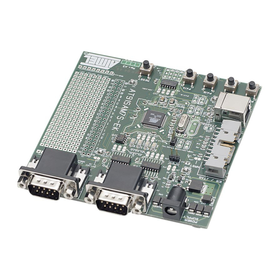
The AT91SAM7S-EK evaluation board enables the evaluation of and code development for applications running on an AT91SAM7Sxx device. This document describes the evaluation board fitted with an AT91SAM7S256. This guide focuses on the AT91SAM7S-EK board as an evaluation platform for the AT91SAM7S family. Deliverables 1.2.1... - Page 6 The user can also evaluate the AT91SAM7S32 with this board. A 48-pin TQFP footprint has been provided for this purpose. To do so, the user must unsolder the AT91SAM7S256 microcontroller (IC4) and fit the AT91SAM7S32 on the 48- pin TQFP footprint (IC5). AT91SAM7S-EK Evaluation Board User Guide 6112C–ATARM–01-Feb-07...
-
Page 7: Setting Up The At91Sam7S-Ek Board
Powering Up the AT91SAM7S-EK is self-powered by the USB port. If the USB port is not used, the card can be supplied by an external DC power supply via the 2.1 mm socket (J1). The polar- Board ity of the power supply is not critical. -
Page 8: At91Sam7S-Ek Block Diagram
Setting Up the AT91SAM7S-EK Board AT91SAM7S-EK Figure 2-1. Block Diagram for AT91SAM7S-EK Board Block Diagram Analog RS232 RS232 Inputs Driver Driver User Pushbuttons User LEDs UART DBGU 1.8V VDDCORE AT91SAM7S256 VDDOUT NRST 3.3V Pushbutton Oscillator, Extension Connector 7 - 14V DC... -
Page 9: Board Description
• Debug Unit (DBGU) – 2-wire UART and Support for Debug Communication Channel interrupt, Programmable ICE Access Prevention • Periodic Interval Timer (PIT) – 20-bit Programmable Counter plus 12-bit Interval Counter • Windowed Watchdog (WDT) AT91SAM7S-EK Evaluation Board User Guide 6112C–ATARM–01-Feb-07... - Page 10 – Double PWM Generation, Capture/Waveform Mode, Up/Down Capability • One Four-channel 16-bit PWM Controller (PWMC) • One Two-wire Interface (TWI) – Master Mode Support Only, All Two-wire Atmel EEPROMs Supported • One 8-channel 10-bit Analog-to-Digital Converter, Four Channels Multiplexed with Digital I/Os ®...
-
Page 11: At91Sam7S256 Block Diagram
NPCS3 TIOB2 MISO MOSI TWCK SPCK ADTRG VDDANA ! 256 Kbytes of internal high-speed Flash Memory ! 64 Kbytes of internal high-speed SRAM Clock Circuitry ! 18.432 MHz standard crystal for the embedded oscillator AT91SAM7S-EK Evaluation Board User Guide 6112C–ATARM–01-Feb-07... -
Page 12: Reset Circuitry
3.12 Wrapping User This allows the developer to fit additional components for prototyping use. Area AT91SAM7S-EK Evaluation Board User Guide 6112C–ATARM–01-Feb-07... -
Page 13: Configuration Straps
Section 4 Configuration Straps Configuration Table 4-1 gives details on configuration straps on the AT91SAM7S-EK evaluation board and their default settings. Strap Table 4-1. Configuration Straps Default Designation Setting Feature Closed Enables the use of the remote DP pull-up (USB) - Page 14 In this case and in order to use the power consumption measure- ment feature, the user has to open the strap by cutting it before soldering a jumper and inserting an anmeter. AT91SAM7S-EK Evaluation Board User Guide 6112C–ATARM–01-Feb-07...
-
Page 15: Schematics
! Board Layout And Silkscreen Printing - Top View ! 64-pin SAM7 Microcontroller (dual footprint) ! 48-pin SAM7 Microcontroller ! Power Supply ! ICE/EXT Connectors ! Device Interface ! PIO ! User PAD Grid AT91SAM7S-EK Evaluation Board User Guide 6112C–ATARM–01-Feb-07... - Page 24 Schematics AT91SAM7S-EK Evaluation Board User Guide 6112C–ATARM–01-Feb-07...
-
Page 25: Revision History
Table 6-1. Change Document Comments Request Ref. 6112A First issue. 6112B New schematics. 1457 6112C Corrected features for JP26 and JP27 in Table 4-1, 3849 “Configuration Straps”. Corrected device label in 64-pin SAM7 schematic. 2734 AT91SAM7S-EK Evaluation Board User Guide 6112C–ATARM–01-Feb-07... - Page 26 Revision History AT91SAM7S-EK Evaluation Board User Guide 6112C–ATARM–01-Feb-07...
- Page 27 Disclaimer: The information in this document is provided in connection with Atmel products. No license, express or implied, by estoppel or otherwise, to any intellectual property right is granted by this document or in connection with the sale of Atmel products. EXCEPT AS SET FORTH IN ATMEL’S TERMS AND CONDI- TIONS OF SALE LOCATED ON ATMEL’S WEB SITE, ATMEL ASSUMES NO LIABILITY WHATSOEVER AND DISCLAIMS ANY EXPRESS, IMPLIED OR STATUTORY...
- Page 28 Mouser Electronics Authorized Distributor Click to View Pricing, Inventory, Delivery & Lifecycle Information: Atmel AT91SAM7S-EK...
Need help?
Do you have a question about the AT91SAM7S-EK and is the answer not in the manual?
Questions and answers