Table of Contents
Advertisement
Quick Links
Advertisement
Table of Contents

Related Manuals for KROHNE SMARTPAT COND 1200


Summary of Contents for KROHNE SMARTPAT COND 1200
- Page 1 SMARTPAT COND 1200 SMARTPAT COND 1200 SMARTPAT COND 1200 Handbook Handbook Handbook Handbook Digital conductive conductivity sensor for the water and wastewater industry Electronic Revision: ER 1.0.0_ (SW.REV 1.0.x) © KROHNE 09/2015 - 4003041501 - MA SMARTPAT COND1200 R01 en...
- Page 2 All rights reserved. It is prohibited to reproduce this documentation, or any part thereof, without the prior written authorisation of KROHNE Messtechnik GmbH. Subject to change without notice. Copyright 2015 by KROHNE Messtechnik GmbH - Ludwig-Krohne-Str. 5 - 47058 Duisburg (Germany) www.krohne.com 09/2015 - 4003041501 - MA SMARTPAT COND1200 R01 en...
-
Page 3: Table Of Contents
CONTENTS SMARTPAT COND 1200 1 Safety instructions 1.1 Intended use ........................5 1.2 Certifications ........................5 1.3 Safety instructions from the manufacturer ..............6 1.3.1 Copyright and data protection ....................6 1.3.2 Disclaimer ..........................6 1.3.3 Product liability and warranty ....................7 1.3.4 Information concerning the documentation................ - Page 4 CONTENTS SMARTPAT COND 1200 6 Service 6.1 Maintenance ........................29 6.1.1 Cleaning ..........................29 6.2 Availability of services ....................29 6.3 Returning the device to the manufacturer..............29 6.3.1 General information......................29 6.3.2 Form (for copying) to accompany a returned device............30 6.4 Disposal ..........................
-
Page 5: Safety Instructions
INFORMATION! The manufacturer is not liable for any damage resulting from improper use or use for other than the intended purpose. The intended use of the sensor SMARTPAT COND 1200 is the measurement of conductivity in conductive liquids. 1.2 Certifications... -
Page 6: Safety Instructions From The Manufacturer
SAFETY INSTRUCTIONS SMARTPAT COND 1200 1.3 Safety instructions from the manufacturer 1.3.1 Copyright and data protection The contents of this document have been created with great care. Nevertheless, we provide no guarantee that the contents are correct, complete or up-to-date. -
Page 7: Product Liability And Warranty
SAFETY INSTRUCTIONS SMARTPAT COND 1200 1.3.3 Product liability and warranty The operator shall bear responsibility for the suitability of the device for the specific purpose. The manufacturer accepts no liability for the consequences of misuse by the operator. Improper installation or operation of the devices (systems) will cause the warranty to be void. The respective "Standard Terms and Conditions"... -
Page 8: Warnings And Symbols Used
SAFETY INSTRUCTIONS SMARTPAT COND 1200 1.3.5 Warnings and symbols used Safety warnings are indicated by the following symbols. DANGER! This warning refers to the immediate danger when working with electricity. DANGER! This warning refers to the immediate danger of burns caused by heat or hot surfaces. -
Page 9: Device Description
DEVICE DESCRIPTION SMARTPAT COND 1200 2.1 Scope of delivery INFORMATION! Inspect the packaging carefully for damages or signs of rough handling. Report damage to the carrier and to the local office of the manufacturer. INFORMATION! Do a check of the packing list to make sure that you have all the elements given in the order. -
Page 10: Device Description
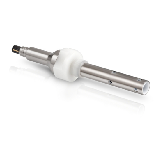
DEVICE DESCRIPTION SMARTPAT COND 1200 2.2 Device description Figure 2-2: Construction of the sensor 1 VP2 connector 2 Nickel-plated brass body 3 Process connection: G3/4 A thread (male), PVDF 4 Electrodes: stainless steel 1.4571 and PVDF (isolator) www.krohne.com 09/2015 - 4003041501 - MA SMARTPAT COND1200 R01 en... -
Page 11: Nameplate
DEVICE DESCRIPTION SMARTPAT COND 1200 2.3 Nameplate ER 1.0.0 Figure 2-3: Example for a nameplate on the sensor body 1 Manufacturer 2 Device name 3 Cell constant / Electronic Revision version 4 TAG number (optional) 5 Order code 6 Serial number 7 Manufacturing date / Ingress protection 8 Electronic/electric device waste marking;... -
Page 12: Installation
INSTALLATION SMARTPAT COND 1200 3.1 General notes on installation DANGER! For devices used in hazardous areas, additional safety notes apply; please refer to the Ex documentation. DANGER! All work on the electrical connections may only be carried out with the power disconnected. -
Page 13: Pre-Installation Requirements
INSTALLATION SMARTPAT COND 1200 3.3 Pre-installation requirements CAUTION! Do not drop the device! Handle the device with care! • Never touch or scratch the electrodes of the sensor. • Store the sensor in its original packaging in a dry, dust-free location. Keep it away from dirt. If •... -
Page 14: Installation Procedure
INSTALLATION SMARTPAT COND 1200 3.4 Installation procedure WARNING! During installation of the device make sure that you use ESD (electrostatic discharge) protection equipment. 1 Connect the sensor to the junction box or directly to the process control system. 2 Install the sensor into its final measuring location. -
Page 15: Electrical Connections
ELECTRICAL CONNECTIONS SMARTPAT COND 1200 4.1 Safety instructions DANGER! For devices used in hazardous areas, additional safety notes apply; please refer to the Ex documentation. DANGER! All work on the electrical connections may only be carried out with the power disconnected. -
Page 16: Grounding And Equipotential Bonding
ELECTRICAL CONNECTIONS SMARTPAT COND 1200 4.3 Grounding and equipotential bonding Sensor type SMARTPAT COND 1200 must be grounded (hard grounding or capacitive connection to ground). SJB 200 W-Ex junction box offers the grounding possibility. For further information refer to the SJB 200 W-Ex manual. -
Page 17: Connecting The Sensor Cable
ELECTRICAL CONNECTIONS SMARTPAT COND 1200 4.5 Connecting the sensor cable DANGER! All work on the electrical connections may only be carried out with the power disconnected. INFORMATION! The cable glands installed by the manufacturer are designed for a cable diameter of 8 to 13 mm. - Page 18 ELECTRICAL CONNECTIONS SMARTPAT COND 1200 ® Figure 4-3: SJB 200 W-Ex with SMARTPAT sensor, display and without integrated HART resistor (left side). ® SJB 200 W-Ex with SMARTPAT sensor, without display and integrated HART resistor (right side) SJB 200 W-Ex with SMARTPAT sensor, display SJB 200 W-Ex with SMARTPAT sensor, ®...
-
Page 19: Installing The Sensor
ELECTRICAL CONNECTIONS SMARTPAT COND 1200 4.7 Installing the sensor 4.7.1 General installation instructions WARNING! Ensure that the pipeline is without pressure before installing or removing a sensor! INFORMATION! During installation you should fix a shut-off valve in front of and behind the instrument so that the sensor can be taken out in case of check. - Page 20 ELECTRICAL CONNECTIONS SMARTPAT COND 1200 Figure 4-5: Installation for clean water 1 Flow direction 2 Ordered sensor • This installation is only recommended if the pipeline is completely filled and if there are no particles or air bubbles in the pipeline.
- Page 21 ELECTRICAL CONNECTIONS SMARTPAT COND 1200 Figure 4-7: Possible installation 1 Flow direction 2 Ordered sensor • This installation is only recommended if the pipeline is completely filled and if there are no particles or air bubbles in the pipeline. • Consider the diameter of the pipeline, i.e. compare pipeline DN with insertion length of the sensor shaft.
-
Page 22: Operation
OPERATION SMARTPAT COND 1200 5.1 Configuration For configuration connect the sensor to the loop and configure the sensor via PACTware FDT/DTM. Otherwise for offline configuration the sensor can be connected to the OPTIBRIDGE/SMARTBRIDGE or another suitable USB interface cable. OPTIBRIDGE/SMARTBRIDGE will be connected to the PC via USB port. Add the devices regarding... -
Page 23: Calibration With Pactware Tm
OPERATION SMARTPAT COND 1200 5.2.1 Calibration with PACTware Calibration • Start the function calibration calibration calibration calibration in menu mode Quick Setup Quick Setup Quick Setup Quick Setup or Setup Setup Setup Setup Select calibration method • Choose Product calibration... - Page 24 OPERATION SMARTPAT COND 1200 • If you want to save the new cell constant press Next Next Next Next to proceed • Set the calibration date with DD-MM-YYYY • Press Next Next to proceed Next Next The message Save value?
-
Page 25: Calibration With Hart ® Handheld 475 Field Communicator
OPERATION SMARTPAT COND 1200 ® 5.2.2 Calibration with HART Handheld 475 FIELD COMMUNICATOR Calibration • Start the function calibration calibration calibration calibration in menu mode Quick Setup Quick Setup Quick Setup Quick Setup or Setup Setup Setup Setup Select calibration method •... - Page 26 OPERATION SMARTPAT COND 1200 The old cell constant and the calculated new cell constant appear • If you want to save the new cell constant press OK OK to proceed • Set the calibration date with MM-DD-YYYY • Press Enter...
-
Page 27: Troubleshooting
OPERATION SMARTPAT COND 1200 5.3 Troubleshooting Problem Possible cause Remedy The conductivity sensor Open circuit or humidity Check the cable wiring of the sensor cable on the junction box. between the connections. Otherwise connect the sensor to the primary master e.g. -
Page 28: Status Messages And Diagnostic Information
OPERATION SMARTPAT COND 1200 5.4 Status messages and diagnostic information Measurements out of specification Message Message Description DD Description DD Description DTM Description DTM Action Action Message Message Description DD Description DD Description DTM Description DTM Action Action Cond. > Max. cond. -
Page 29: Service
SERVICE SMARTPAT COND 1200 6.1 Maintenance 6.1.1 Cleaning The conductive conductivity electrodes are in direct contact with the medium. Regular cleaning must therefore be performed, relative to the susceptibility of the medium to contamination! All suitable, common household cleaning chemicals can be used for cleaning. Abrasive cleaners... -
Page 30: Form (For Copying) To Accompany A Returned Device
SERVICE SMARTPAT COND 1200 6.3.2 Form (for copying) to accompany a returned device CAUTION! To avoid any risk for our service personel, this form has to be accessible from outside of the packaging with the returned device. Company: Address: Department: Name: Tel. -
Page 31: Technical Data
TECHNICAL DATA SMARTPAT COND 1200 7.1 Measuring principle 7.1.1 Conductivity measurement Figure 7-1: Measuring principle for conductivity measurement 1 Flow direction 2 Inner electrode 3 Outer electrode 4 Power supply Conductivity is defined as the property of an aqueous solution to conduct electricity by ion transportation. -
Page 32: Technical Data
TECHNICAL DATA SMARTPAT COND 1200 7.2 Technical data INFORMATION! The following data is provided for general applications. If you require data that is more • relevant to your specific application, please contact us or your local sales office. Additional information (certificates, special tools, software,...) and complete product •... - Page 33 TECHNICAL DATA SMARTPAT COND 1200 Communication Measuring range 0.1...20 mS/cm at 25°C / 77°F (for c=1 the displayed unit is mS/cm for conductivity and kOhm*cm for resistivity) Output signal 4...20 mA (passive) Output resolution 20 µA Field communication ® HART...
-
Page 34: Dimensions
TECHNICAL DATA SMARTPAT COND 1200 7.3 Dimensions Figure 7-2: SMARTPAT COND 1200 Process connection G3/4 A thread (male) Dimensions [mm] Dimensions [inch] 228.2 8.98 7.79 0.28 4.57 3.94 Ø20.5 Ø0.81 VarioPin Ø24 Ø0.94 WS 36 G3/4 A Ø45 Ø1.77 Ø20 Ø0.79... -
Page 35: Description Of Hart Interface
DESCRIPTION OF HART INTERFACE SMARTPAT COND 1200 8.1 General description ® The open HART protocol, which can be used for free, is integrated into the sensor for communication. ® Devices which support the HART protocol are classified as either operating devices or field devices. -
Page 36: Connection Variants
DESCRIPTION OF HART INTERFACE SMARTPAT COND 1200 8.3 Connection variants CAUTION! For installation in a multidrop communication system please consider the voltage drop for the 250 Ω loop resistance for HART ® communication. The supply voltage has to be adjusted. -
Page 37: Point-To-Point Connection - Analogue / Digital Mode
DESCRIPTION OF HART INTERFACE SMARTPAT COND 1200 8.3.1 Point-to-Point connection - analogue / digital mode ® Point-to-Point connection between the sensor and the HART Master. The current output of the device is passive. Figure 8-1: Point- to-Point connection 1 Primary master with e.g. PACTware... -
Page 38: Inputs/Outputs And Hart ® Dynamic Variables And Device Variables
DESCRIPTION OF HART INTERFACE SMARTPAT COND 1200 ® 8.4 Inputs/outputs and HART dynamic variables and device variables ® HART dynamic variable Conductivity (Resistivity) Resistivity (Conductivity) Temperature Code = device variable code Code Type ® HART device variable Conductivity linear Resistivity... -
Page 39: Field Device Tool / Device Type Manager (Fdt/Dtm)
DESCRIPTION OF HART INTERFACE SMARTPAT COND 1200 8.6 Field Device Tool / Device Type Manager (FDT/DTM) A Field Device Tool Container (FDT Container) is basically a PC program used to configure a field ® device via HART . To adapt different devices, the FDT container uses a so-called Device Type Manager (DTM). -
Page 40: Basic-Dd Menu Tree (Details For Settings)
DESCRIPTION OF HART INTERFACE SMARTPAT COND 1200 8.8 Basic-DD menu tree (details for settings) 1 Measuring value 1 Conductivity ® Display of the measured conductivity value on process control system, HART handheld or SMARTMAC 200 W. 2 Resistivity ® Display of the measured resistivity value on process control system, HART handheld or SMARTMAC 200 W. - Page 41 DESCRIPTION OF HART INTERFACE SMARTPAT COND 1200 4 Setup 1 Process input 1 Temperature 1 Temperature unit (set and display) 2 Temperature offset (set and display) 3 Date of offset (read only) 4 Temp. compensation (set and display) (off, linear and natural water. Default: linear) 5 Temp.
- Page 42 DESCRIPTION OF HART INTERFACE SMARTPAT COND 1200 4 Device 1 Information 1 Sensor information 1 Order code (read only) 2 Device name 3 Serial number ® 4 HART 5 Polling address 6 Manufacturer ID 7 Date of manufacturing 8 SW version...
-
Page 43: Notes
NOTES SMARTPAT COND 1200 09/2015 - 4003041501 - MA SMARTPAT COND1200 R01 en www.krohne.com... - Page 44 • Process Analysis • Services Head Office KROHNE Messtechnik GmbH Ludwig-Krohne-Str. 5 47058 Duisburg (Germany) Tel.: +49 203 301 0 Fax: +49 203 301 10389 info@krohne.com The current list of all KROHNE contacts and addresses can be found at: www.krohne.com...
Need help?
Do you have a question about the SMARTPAT COND 1200 and is the answer not in the manual?
Questions and answers