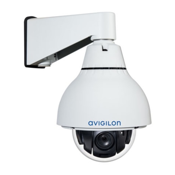
Motorola Avigilon H4 Series Installation Manual
Ptz dome camera
Hide thumbs
Also See for Avigilon H4 Series:
- Installation manual (30 pages) ,
- Installation manual (30 pages)

Related Manuals for Motorola Avigilon H4 Series


Summary of Contents for Motorola Avigilon H4 Series
-
Page 1: Installation Guide
Installation Guide Avigilon™ H4 PTZ Dome Camera Models: 1.0C-H4PTZ-DC45 and 2.0C-H4PTZ-DC30... - Page 2 Important Safety Information This manual provides installation and operation information and precautions for the use of this device. Incorrect installation could cause an unexpected fault. Before installing this equipment read this manual carefully. Please provide this manual to the owner of the equipment for future reference. This Warning symbol indicates the presence of dangerous voltage within and outside the product enclosure that may result in a risk of electric shock, serious injury or death to persons if proper precautions are not followed.
-
Page 3: Legal Notices
This equipment has been tested and found to comply with the limits for a Class B digital device, pursuant to Part 15 of the FCC rules. These limits are designed to provide reasonable protection against harmful interference in a residential installation. This equipment generates, uses and can radiate radio frequency energy and, if not installed and used in accordance with the instructions, may cause harmful interference to radio communications. - Page 4 Disclaimer This document has been compiled and published using product descriptions and specifications available at the time of publication. The contents of this document and the specifications of the products discussed herein are subject to change without notice. Avigilon Corporation reserves the right to make any such changes without notice.
-
Page 5: Table Of Contents
Table of Contents Overview Front View Side View Installation Camera Package Contents Installation Steps Preparing the Camera for Installation (Optional) Configuring SD Card Storage (Optional) Cutting the Mounting Hole (Optional) Attaching the Back Panel for Plenum Installation Connecting Cables Initializing a Camera Username and Password Assigning an IP Address Accessing the Live Video Stream Mounting the PTZ Dome Camera... -
Page 6: Overview
Overview Front View 1. Serial number tag Device information, product serial number and part number label. 2. Connection status LED indicator Provides information about device operation. For more information, see Connection Status LED Indicator on page 18. 3. Link LED indicator Indicates if there is an active connection in the Ethernet port. -
Page 7: Side View
Side View 1. Ethernet port Accepts an Ethernet connection to a network. Server communication and image data transmission occurs over this connection. Also receives power when it is connected to a network that provides Power over Ethernet. 2. Power connector block Accepts a terminal block with either an AC or DC power connection. - Page 8 7. Lanyard anchor Safety lanyards can attach to anchors at the top of each clamp to help prevent the camera from falling. Side View...
-
Page 9: Installation
Installation Camera Package Contents Ensure the camera package contains the following: Avigilon H4 PTZ Dome Camera Back panel Mounting template sticker Terminal block I/O connector block Installation Steps Complete the following sections to install the device. Preparing the Camera for Installation Note: Be careful not to scratch the dome bubble. - Page 10 3. Remove the protective material inside the dome cover. 4. If you are planning to use onboard storage, insert an SD card into the SD card slot on the PTZ camera. For more information, see (Optional) Configuring SD Card Storage on the next page.
-
Page 11: (Optional) Configuring Sd Card Storage
5. Use a screw driver to push each of the clamps into the dome camera until the spring is fully compressed, then turn the clamp into the ready position. (Optional) Configuring SD Card Storage To use the camera's SD card storage feature, you must insert an SD card into the card slot. It is recommended that the SD card have a capacity of 8 GB or more and a write speed of class 610 or better. -
Page 12: (Optional) Attaching The Back Panel For Plenum Installation
1. Use the mounting template to cut a hole in the mounting surface. 2. Remove the mounting template and pull the required cables through the mounting hole. (Optional) Attaching the Back Panel for Plenum Installation If you are installing the dome camera into a plenum space, install the back panel. (Optional) Attaching the Back Panel for Plenum Installation... -
Page 13: Connecting Cables
1. Attach a conduit connector to the cable entry hole on the back panel. Install the conduit and its fitting as instructed by the manufacturer. 2. Pull the required cables through the conduit, then through the cable entry hole in the back panel. Figure 1: Cables going through the conduit connector (1) and the back panel (2). -
Page 14: Initializing A Camera Username And Password
Note: The PTZ will move as the camera powers up. It will stop when it has completed its startup procedures. 4. Connect a network cable to the Ethernet port (RJ-45 connector). The Link LED indicator will turn on once a network link has been established. 5. -
Page 15: Assigning An Ip Address
Assigning an IP Address The camera automatically obtains an IP address when it is connected to a network. Note: If the camera cannot obtain an IP address from a DHCP server, it will use Zero Configuration Networking (Zeroconf) to choose an IP address. When set using Zeroconf, the IP address is in the 169.254.0.0/16 subnet. -
Page 16: Mounting The Ptz Dome Camera
Cameras manufactured after January 1, 2020: these cameras do not have a default username or password and will be in a factory default state. You must create a user with administrator privileges before the camera is operational. For more information, see Initializing a Camera Username and Password on page 9. -
Page 17: Installing The Dome Cover
Figure 2: Releasing the clamp from ready position. Installing the Dome Cover 1. Align the notches on the dome cover with the release tab on the base. The dome cover should be flush against the camera base. 2. Slide the dome cover clockwise until it locks into place. Note: Be careful not to scratch the dome bubble. -
Page 18: Cable Connections
Cable Connections Connecting External Power If PoE is not available, the camera needs to be powered through the removable power connector block. Refer to the diagrams in this guide for the location of the power connector block. The power consumption information is listed in the product specifications. To connect power to the power connector block, complete the following steps: 1. -
Page 19: Connecting To Microphones, Speakers, And Video Monitors
Figure 3: Example application. 1. +12 VDC, 50 mA max. output for relay drive 2. Relay ground return 3. Relay input 1 4. Relay input 2 5. Relay Output 1 6. Relay Output 2 * — Relay ** — Switch Note: The 12 V connection can be used to energize a relay coil with up to 50 mA. - Page 20 Only the 2.0 megapixel models can be connected to an external video monitor through the A/V connector. Note: The camera only supports line level mono audio input and an NTSC or PAL video output. The video output signal is determined by the camera flicker control setting. When the camera flicker control is set to 60 Hz, the video output signal is NTSC.
-
Page 21: Setting The Home Preset Position
Setting the Home Preset Position The PTZ camera supports self-learning video analytics from the home preset position. The home preset position is typically the field of view the PTZ camera returns to after being used for investigations. Before you can configure the camera's home position, you must connect the camera to a site in the ACC™ Client software. - Page 22 On the Select Rule Event(s) page, select PTZ idle. On the Select Rule Action(s) page, select Go to Home Preset. Automatically Returning to the Home Position...
-
Page 23: Connection Status Led Indicator
Connection Status LED Indicator Once connected to the network, the Connection Status LED indicator will display the progress in connecting to the Network Video Management software. The following table describes what the LED indicator shows: Connection State Connection Status Description LED Indicator Obtaining One short flash... -
Page 24: Resetting To Factory Default Settings
Resetting to Factory Default Settings If the device no longer functions as expected, you can choose to reset the device to its factory default settings. Use the firmware revert button to reset the device. The firmware revert button is shown in the following diagram: Note: Be careful not to scratch the dome bubble. -
Page 25: Setting The Ip Address Using The Arp/Ping Method
Setting the IP Address Using the ARP/Ping Method Complete the following steps to configure the camera to use a specific IP address: 1. Locate and copy down the MAC Address (MAC) listed on the Serial Number Tag for reference. 2. Open a Command Prompt window and enter the following commands: a. -
Page 26: Cleaning
Cleaning Dome Bubble If the video image becomes blurry or smudged in areas, it may be because the dome bubble requires cleaning. To clean the dome bubble: Use hand soap or a non-abrasive detergent to wash off dirt or fingerprints. Use a microfiber cloth or non-abrasive fabric to dry the dome bubble. -
Page 27: Limited Warranty And Technical Support
Limited Warranty and Technical Support Avigilon warranty terms for this product are provided at avigilon.com/warranty. Warranty service and technical support can be obtained by contacting Avigilon Technical Support: avigilon.com/contact-us/. Limited Warranty and Technical Support...
Need help?
Do you have a question about the Avigilon H4 Series and is the answer not in the manual?
Questions and answers