SCHUNK RSS R1 Assembly And Operating Manual
Radio sensor system rss, receiver, transmitter
Hide thumbs
Also See for RSS R1:
- Translation of the original manual (44 pages) ,
- Assembly and operating manual (28 pages) ,
- Assembly and operating manual (34 pages)

Subscribe to Our Youtube Channel
Related Manuals for SCHUNK RSS R1


Summary of Contents for SCHUNK RSS R1
- Page 1 Translation of the original manual Assembly and Operating Manual Radio sensor system RSS Receiver RSS R1 (ID-No.: 377700) Transmitter RSS T2 (ID-No.: 377715)
- Page 2 Imprint Copyright: This manual is protected by copyright. The author is SCHUNK GmbH & Co. KG. All rights reserved. Any reproduction, processing, distribution (making available to third parties), translation or other usage - even excerpts - of the manual is especially prohibited and requires our written approval.
-
Page 3: Table Of Contents
Information on radio link and range.............. 14 Assembly ........................ 15 Assembly of the transmitter RSS T2 .............. 15 Assembly and electrical connection of the RSS R1 receiver ....... 16 Start-up ........................ 17 General information on commissioning ............. 17 Programming the transmitter to the receiver ............ 18 Testing the antenna position................ - Page 4 Table of Contents 6.1.8 Delete transmitter ID................ 25 6.1.9 Signaling the distance between signals or the signal strength.... 25 6.1.10 Setting the limit value for battery monitoring........ 26 6.1.11 Setting the output behaviour .............. 26 6.1.12 Teaching the limit value (teaching threshold) ........ 26 6.1.13 Setting the watchdog time .............. 27 6.1.14 Function of the DIP 5 Extension of the reception range during the learning procedure ................. 28 6.1.15 Manual setting of transmitter ID (programming)........ 29...
-
Page 5: General
• General terms of business* • Catalog data sheet of the purchased product * The documents marked with an asterisk (*) can be downloaded on our homepage schunk.com 03.00 | Radio sensor system RSS | Assembly and Operating Manual | en | 0389609... -
Page 6: Warranty
General 1.2 Warranty If the product is used as intended, the warranty is valid for 24 months from the ex-works delivery date under the following conditions: • Observe the applicable documents, Applicable documents 5] • Observe the ambient conditions and operating conditions, Environmental and operating conditions 7] Parts touching the workpiece and wear parts are not included in... -
Page 7: Basic Safety Notes
• Structural changes should only be made with the written approval of SCHUNK. 2.3 Environmental and operating conditions • Make sure that the product is a sufficient size for the application. -
Page 8: Personnel Qualification
Basic safety notes • Within the range of 868.3 MHz, the system does not correspond to the EMC regulation for radio wave penetration immunity. A loss of wireless telegrams may occur in this range. If the antenna is at a distance of over 25 cm from the receiver, the probability of interference increases. -
Page 9: Notes On Safe Operation
Basic safety notes The following personal qualifications are necessary for the various activities related to the product: Trained electrician Due to their technical training, knowledge and experience, trained electricians are able to work on electrical systems, recognize and avoid possible dangers and know the relevant standards and regulations. -
Page 10: Disposal
Basic safety notes 2.7 Disposal Handling of disposal The incorrect handling of disposal may impair the product's safety and cause serious injuries as well as considerable material and environmental harm. • Follow local regulations on dispatching product components for recycling or proper disposal. 2.8 Fundamental dangers General •... - Page 11 Basic safety notes • The operator must ensure that all components and assembly groups are included in the local potential equalisation in accordance with the applicable regulations. • While paying attention to the actual conditions of the working environment, the potential equalisation must be implemented by a specialist electrician according to the applicable regulations.
-
Page 12: Technical Data
Technical data 3 Technical data More technical data is included in the catalog data sheet. Whichever is the latest version. 3.1 Technical Data RSS-R1 Receiver ID number 0377700 Receiving frequency [MHz] 868.3 Nominal voltage [VDC] Min. voltage [V] Max. voltage [V] Max. -
Page 13: Technical Data - Rss-T2
Technical data 3.2 Technical data - RSS-T2 ID number 0377715 Transmission frequency [MHz] 868.3 Sensor connection 2x M8 Integrated voltage supply Lithium batterie Housing material Protocol Enocean Standard IP rating Ambient temperature [°C] Min. Max. Weight [kg] 0,16 03.00 | Radio sensor system RSS | Assembly and Operating Manual | en | 0389609... -
Page 14: Information On Radio Link And Range
Technical data 3.3 Information on radio link and range The transmitter sends telegrams with 868 MHz to the receiver. The receiver checks the incoming telegrams and uses them to control its outputs. This radio link is principally prone to interferences by other radio systems or systems emitting radio signals. -
Page 15: Assembly
Assembly 4 Assembly 4.1 Assembly of the transmitter RSS T2 Install the housing in a suitable position next to the sensor Ø fastening using two screws M4. - Install the sensor (closer) at the gripper. Ø Fasten the M8 sensor plugs with screws to the transmitter. Ø... -
Page 16: Assembly And Electrical Connection Of The Rss R1 Receiver
Assembly 4.2 Assembly and electrical connection of the RSS R1 receiver Mount the receiver in a switching cabinet located less then 10 Ø m from the transmitter by snapping it onto a DIN track (EN50022). Connect the receiver: Ø Antenna socket X1: - SMA socket for external antenna (we recommend our RSS-R-A antenna, ID No. -
Page 17: Start-Up
Start-up 5 Start-up 5.1 General information on commissioning Check for any damage caused during transport before commissioning the product. In the case of mechanical damage, the product may not be put into operation. Read the Assembly and Operating Manual carefully, observe the technical information and the applicable national legal requirements. -
Page 18: Programming The Transmitter To The Receiver
WD LED. With DIP 8 switched off, the time can be varied between 0 and one second. SCHUNK recommends setting the time to 15 seconds with DIP 8 switched on. -
Page 19: Functional Description
Functional description 6 Functional description 6.1 RSS-R1 6.1.1 General discription Block diagram of the receiver A power supply of 12 to 24 V DC is required to operate the wireless receiver. It is connected using plug connectors with Cage Clamp® connections. An external magnetic antenna is required to receive wireless telegrams for the frequency range of 868 MHz. - Page 20 Functional description Teach-in mode In teach-in mode (activated by DIP 1 ON/OFF), the ID of a detected EnOcean telegram is stored in the receiver and the teach-in mode is automatically ended. If no valid telegram from a transmitter is received in the teach-in mode after 15 s have elapsed, this is signaled as a faulty status.
-
Page 21: Led
Functional description 6.1.2 LED LED (color) Status Meaning US (green) Power supply status • no power supply available • 24 V DC OK WD (red) Status system check and operating mode • Operating condition active (reception active) Off / flash 15 ms "flash"... -
Page 22: Measuring Jacks
Functional description 6.1.3 Measuring jacks Designation Type Meaning Potentiometer Adjustment of time and limit value (value accepted with DIP switch) Jack Measuring jack to adjust the watchdog and limit values ac-cording to voltage diagram Jack Reference potential 6.1.4 Function description delivery condition After first switching on the voltage supply, the receiver module is in the “INACTIVE”... -
Page 23: Status Definition
Functional description 6.1.5 Status definition Status Description INACTIVE During commissioning, the switching actuator signals a missing assignment (status: inactive) to the sensor by a blinking watchdog LED (2Hz). No ID of a sensor has been “learned" yet. The “inactive” status can be restored by switching on the DIP switch “Delete ID”... -
Page 24: Time Response
Functional description 6.1.6 Time response The time lag between measurable telegrams must be at least 50 ms. 6.1.7 Function of the DIP switch Switch Meaning Type / function / code designation 8-pin DIP switch 1 OFF / ON Delete transmitter ID and activate teach-in mode = ON * 2 OFF / ON OFF = SI LED displays distance between signals ON = SI LED shows signal levels... -
Page 25: Delete Transmitter Id
Functional description 6.1.8 Delete transmitter ID To learn a new transmitter, the DIP 1 must be momentarily switched to “ON” (assignment function). Any previously learned transmitter will be deleted and cannot be learned for approx. 30 minutes thereafter (☞ see list of deleted transmitters). For further behaviour, see ☞... -
Page 26: Setting The Limit Value For Battery Monitoring
Functional description 6.1.10 Setting the limit value for battery monitoring Einst. Poti set up Poti limit value setting 2,5 V dec 255 100 % 3,6 U batt 255 dec Limit value setting The current potentiometer value is stored when switching on DIP switch 3 at status of “ACTIVE”... -
Page 27: Setting The Watchdog Time
Functional description 6.1.13 Setting the watchdog time set up Poti Einst. Poti set up Poti System time setting limit value setting 2,5 V dec 255 100 % system 1s (8=OFF) 3,6 U batt 35s (8=ON) 255 dec Setting the watchdog time The POTI value is saved by turning on of the DIP switch 4 at status “ACTIVE”... -
Page 28: Function Of The Dip 5 Extension Of The Reception Range During The Learning Procedure
Functional description 6.1.14 Function of the DIP 5 Extension of the reception range during the learning procedure By switching on DIP 5, the range reduction to 5 m in learning mode can be switched off, i.e. the full reception range of the receiver is then used for learning, e.g. -
Page 29: Manual Setting Of Transmitter Id (Programming)
Functional description 6.1.15 Manual setting of transmitter ID (programming) If DIP 3 and DIP 4 are activated at the same time in the INACTIVE status, the switching actuator is set in the programming mode. When setting the first ID byte (ID0), the LC-LED flashes red (incl. output) with 0.5 Hz for 10 s. -
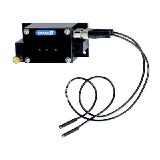
Page 30: Rss-T2
Functional description 6.2 RSS-T2 6.2.1 Operation The transmitter module is not equipped with conventional control elements. Two reed switches are integrated instead, which can be operated via screw fastened magnetic brackets. Unscrew the magnetic bracket of its present position. Screw in the magnetic bracket into the desired position again. -
Page 31: Led - Display
Functional description 6.2.3 LED - Display DesignationLED Meaning D01 light luminous The sensor 1 is actuated. The contact of the sensor is closed. D02 light luminous The sensor 2 is actuated. The contact of the sensor is closed. A radiogram is sent just now. 03.00 | Radio sensor system RSS | Assembly and Operating Manual | en | 0389609... -
Page 32: Maintenance And Care
The system is maintenance-free. Only the life span of the transmitter is limited by the battery installed Technical data 12]. To change the battery, contact SCHUNK Service. 03.00 | Radio sensor system RSS | Assembly and Operating Manual | en | 0389609...
Need help?
Do you have a question about the RSS R1 and is the answer not in the manual?
Questions and answers