
Related Manuals for Garmin GTX 335 w GPS


Summary of Contents for Garmin GTX 335 w GPS
- Page 1 GTX 335 w/GPS Installation Guidance From STC SA01714WI 190-00734-17 March 2017 Revision 1...
- Page 2 Garmin. Garmin hereby grants permission to download a single copy of this manual and of any revision to this manual onto a hard drive or other electronic storage medium to be viewed and to...
- Page 3 United States without first obtaining an export license. Information in this document can change without notice. Go to Garmin’s website www.garmin.com updates and supplemental information about the operation of Garmin units.
- Page 4 California to cause cancer, birth defects, or reproductive harm. This notice is being provided in accordance with California's Proposition 65. If you have any questions or would like more information, please refer to our website at www.garmin.com/prop65. WARNING Perchlorate Material – special handling may apply.
-
Page 5: Table Of Contents
2.1 Operational Limitations ........................2-1 2.2 Installation Limitations .........................2-1 3 INSTALLATION OVERVIEW ......................3-1 3.1 Pre-Installation Information ......................3-2 3.2 Garmin Available Installation Materials ..................3-3 3.3 Installation Materials Not Supplied ....................3-3 3.4 Installation Considerations ......................3-4 3.5 GTX Series Minimum System Configurations ................3-4 3.6 Crimping Tools ..........................3-4 3.7 Test Equipment ..........................3-4... - Page 6 C EQUIPMENT COMPATIBILITY AND CONFIGURATION ........C-1 PPENDIX C.1 Altitude Source ..........................C-2 C.2 Audio Panels ..........................C-4 C.3 TIS-A Traffic Display ......................... C-5 C.4 Garmin GTS Traffic Interface Configuration ................C-5 C.5 Discrete Configuration ........................ C-5 D ACCEPTABLE HARDWARE ..................D-1 PPENDIX 190-00734-17 GTX 335 w/GPS Installation Guidance Rev.
- Page 7 LIST OF FIGURES Figure 1-1 GTX 335 Interface Summary ....................1-6 Figure 1-2 GTX 335 Front Panel .......................1-7 Figure 1-3 GAE ............................1-10 Figure 3-1 GPS Antenna Location (GTX 335 with SBAS/GPS) ............3-11 Figure 3-2 Electrical Bond Preparation - Nut Plate .................3-17 Figure 3-3 Electrical Bond Preparation - Bolt/Nut Joint .................3-17 Figure 3-4 Electrical Bond Preparation - Terminal Lug ................3-17 Figure 3-5 Bonding Strap ........................3-19...
- Page 8 Table 1-2 GTX 335 Pre-Installation Checklist ..................1-11 Table 1-3 Electrical Load ........................1-12 Table 1-4 Garmin Documents .........................1-12 Table 1-5 Garmin Documents Available Upon Request .................1-12 Table 1-6 Federal Aviation Administration Documents .................1-13 Table 1-7 Industry Standards ........................1-13 Table 3-1 GTX 335 Connector Kit Options ....................3-3 Table 3-2 GTX 335 Backplate Assembly Options ..................3-3...
- Page 9 1 GENERAL DESCRIPTION Introduction............................1-2 Terminology............................1-2 Scope..............................1-4 1.3.1 Approved Aircraft, Systems, and Equipment................1-4 System Overview..........................1-5 1.4.1 GTX 335 Interface ........................1-6 1.4.2 GAE............................1-10 System Installation..........................1-11 1.5.1 Pre-Installation Checklist ......................1-11 Technical Specifications .........................1-12 1.6.1 Power Requirements .......................1-12 1.6.2 Environmental Qualification Form ..................1-12 Reference Documentation.......................1-12 STC Permission ..........................1-13 190-00734-17 GTX 335 w/GPS Installation Guidance...
-
Page 10: Introduction
If you choose to apply the STC to the aircraft or cover additional interfaces other than the data provided herein, the panel mount GTX 335 with GPS must be installed in accordance with the complete version of the Part 23 AML STC installation manual. The additional data must be requested through the Garmin dealer supplying the equipment. - Page 11 Electromagnetic Interference Extended Squitter Environmental Qualification Form Federal Aviation Administration Federal Communications Commission Garmin Altitude Encoder Garmin Display Unit Garmin Navigation System GNSS Global Navigation Satellite System Global Positioning System Garmin Touch Navigator Garmin Transponder HIRF High Intensity Radio Field...
-
Page 12: Scope
Part 23 AML STC SA01714WI to install the equipment in table 1-1. Table 1-1 GTX 335 Unit List Unit Description Black front, panel mounted, extended squitter with internal GTX 335 GPS 011-03300-40 GPS source Altitude Encoder, Garmin (GAE) 011-03080-00 190-00734-17 GTX 335 w/GPS Installation Guidance Rev. 1 Page 1-4... -
Page 13: System Overview
1. Current FAA guidance allows multiple ADS-B Out transmissions on both links if the ICAO aircraft identifier is provided on both systems. 2. Garmin recommends all ADS-B out systems be fully compliant at the time the aircraft is equipped with any fully complaint ADS-B out system. This can be accomplished by either disabling the earlier version of ADS-B out, or upgrading it to also meet full compliance requirements. -
Page 14: Figure 1-1 Gtx 335 Interface Summary
Bottom Antenna Squat Switch Temperature GPS Antenna External Ident Altitude Source GTX 335 Air Data Source Garmin Altitude Encoder Keep Alive Input Power/Ground Legend New LRU Existing LRU Figure 1-1 GTX 335 Interface Summary The following provides detail regarding the panel function of the GTX 335. Refer to GTX 3X5 Pilot's Guide or GTX 33X and GTX 3X5 ADS-B Maintenance Manual for more information about the controls and their functions. -
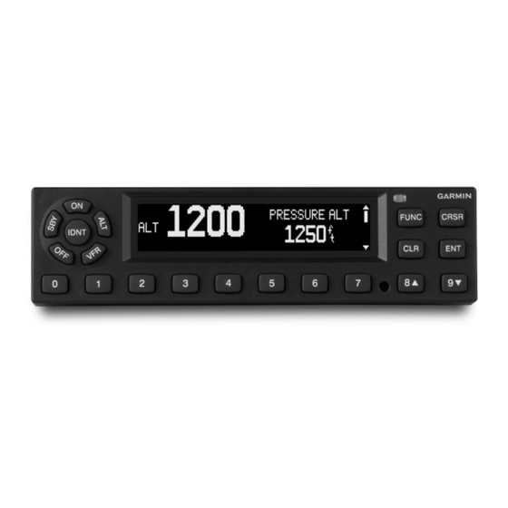
Page 15: Figure 1-2 Gtx 335 Front Panel
Figure 1-2 GTX 335 Front Panel NOTE If the transponder is in the ON or ALT operating mode, the transponder becomes an active part of the Air Traffic Control Radar Beacon System (ATCRBS). The transponder will reply to interrogations from aircraft with TCAS installed. Key Selection Functions for GTX 335: Turn off the GTX 335. - Page 16 VFR key again to restore the identification code used before. FUNC In normal mode, push the FUNC key to change the subpage group shown on the right side of the display. Sub-pages include: Flight ID, Pressure Altitude, Flight Time, Altitude Monitor, System Count Up, and Count Down Timers.
- Page 17 SAT/DALT Shows when the GTX 335 is configured with temperature input. Shows Static Air Temperature and Density Altitude. CONTRAST/OFFSET Contrast is controlled by the 8 and 9 keys. BACKLIGHT/OFFSET This page is displays when photocell backlighting mode is selected in Configuration mode.
-
Page 18: Gae
1.4.2 The GAE module supplies the required barometric altitude source for ADS-B Out compliance. The sensor module has an orifice that allows the module to be connected to the static system. The GAE attaches to the rear connector plate with two screws, and has short, unshielded wires to connect to the GTX 335 unit through the rear D-sub connector with the same connection as the configuration module. -
Page 19: System Installation
1.5 System Installation This section gives equipment information to install the GTX system and related hardware. For interconnect diagrams, refer to section B. 1.5.1 Pre-Installation Checklist Before beginning a GTX system installation the installer must make sure the aircraft meets the prerequisites for the installation of the GTX system under this STC. -
Page 20: Technical Specifications
190-00734-11 AFMS, GTX 33X and GTX 3X5 AML STC 190-00734-15 GTX 3X5 Series Transponder Pilot’s Guide 190-01499-00 Table 1-5 Garmin Documents Available Upon Request Document GTX 3XX Part 23 AML STC Installation Manual 190-00734-10 GTX 3X5 TSO Installation Manual 190-01499-02... -
Page 21: Stc Permission
Table 1-6 Federal Aviation Administration Documents Document FAA Advisory Circular, Airworthiness Approval of Automatic Dependent Surveillance- AC 20-165( ) Broadcast (ADS-B) Out Systems FAA Advisory Circular, Guide for Obtaining a Supplemental Type Certificate AC 21-40A FAA Advisory Circular, System Safety Analysis and Assessment for Part 23 Airplanes AC 23.1309-1E FAA Advisory Circular, Acceptable Methods, Techniques, and Practices - AC 43.13-1B... -
Page 22: Limitations
2 LIMITATIONS Operational Limitations ........................2-1 Installation Limitations ........................2-1 2.2.1 Equipment Interfaced to the GTX ....................2-1 2.2.2 Preservation of Certified Systems ....................2-2 2.2.3 Major Alterations ........................2-2 2.2.4 Antennas.............................2-2 2.2.5 Pressurized Aircraft........................2-2 2.1 Operational Limitations through the single-use registration code Refer to the AFMS for operational limitations. It is available process. - Page 23 2.2.2 Preservation of Certified Systems It is the responsibility of the installer using the data provided in this STC to preserve the essential characteristics of the aircraft in accordance with the aircraft manufacturer’s original design and the requirements of 14 CFR Part 23. 2.2.3 Major Alterations The installation of the GTX 335 system is a major alteration to the aircraft type design.
-
Page 24: Installation Overview
3 INSTALLATION OVERVIEW Pre-Installation Information......................3-2 Garmin Available Installation Materials...................3-3 Installation Materials Not Supplied ....................3-3 Installation Considerations .......................3-4 GTX Series Minimum System Configurations.................3-4 Crimping Tools ..........................3-4 Test Equipment ..........................3-4 External Sensors, Devices, and Interface Considerations..............3-5 3.8.1 Mutual Suppression Bus......................3-5 3.8.2 Altitude Source (Required) ......................3-5 3.8.3... -
Page 25: Pre-Installation Information
3.1 Pre-Installation Information NOTE Always use common avionics installation practices. Refer to FAA Advisory Circulars (ACs) AC 43.13-1B, AC 43.13-2B, or later approved revisions. Complete the applicable pre-installation checklist in section 1.5. Installation planning steps: 1. Complete an electrical load analysis on the aircraft to make sure that the aircraft electrical system can carry the GTX electrical load. -
Page 26: Garmin Available Installation Materials
3.2 Garmin Available Installation Materials Refer to the tables below for a list of available Garmin standard kit items. Table 3-1 GTX 335 Connector Kit Options Unit Item GTX 335 Connector Kit 011-02977-00 Table 3-2 GTX 335 Backplate Assembly Options... -
Page 27: Installation Considerations
3.4 Installation Considerations NOTE Installation instructions are for use in synchronization with the avionics installation practices in AC 43.13-1B, AC 43.13-2B, and FAA approved revisions. Installation considerations: Installation of a GTX 335 system may require the avionics shelves to be changed, or require a new structure. -
Page 28: External Sensors, Devices, And Interface Considerations
3.8 External Sensors, Devices, and Interface Considerations Install sensors in accordance with the sensor manufacturer's data. This manual does not give data for the installation of any external sensors or devices. Refer to appendix C for a list of the permitted types of inputs available. -
Page 29: Gps Source
3.8.3 GPS Source The GTX 335 has an internal GPS/SBAS source for ADS-B Out. The GTX 3X5 receives data from the internal GPS receiver: Latitude Longitude Height above ellipsoid Horizontal and vertical position accuracy data Horizontal position integrity data North/south velocity East/west velocity Up/down velocity Ground speed... -
Page 30: Placards/Labels
3.8.4 Installation with Other ADS-B Out Systems If the GTX 335 transponder is being installed in an aircraft with other ADS-B Out capable equipment, the other ADS-B Out equipment should be Version 2 compliant (TSO-C166b/RTCA DO-260B or TSO-C154c/DO-282B). The UAT or 1090 ES transmit functionality of a Version 1 compliant system should be disabled if it is not upgraded to be Version 2 compliant. -
Page 31: Antenna Considerations
This STC does not install the transponder antenna. The transponder antenna(s) is existing equipment.If an existing GTX transponder is already installed, no changes to the antenna or coax are required. When upgrading from a non-Garmin transponder, the existing approved transponder antenna should be verified to meet these requirements: •... -
Page 32: Table 3-9 Coaxial Cable Specifications
Antenna performance is very important to successful operation with the internal GPS/SBAS receiver. Refer to table 3-11 for approved SBAS/GPS antennas that meet Garmin's minimum performance specifications. Refer to table 3.11.2 for antenna location information to verify an existing antenna location is satisfactory for use with the GTX 335 transponder. -
Page 33: Table 3-11 Gtx 335 Gps Antennas
When a combination antenna is attached, the recommended distance of two feet or more is not applicable to the distance between the antenna elements (e.g., GPS and COM, GPS and SiriusXM). This is provided that the combination antenna is TSO authorized and has been tested to meet Garmin's minimum performance standards. -
Page 34: Figure 3-1 Gps Antenna Location (Gtx 335 With Sbas/Gps)
ANTENNA MASKED BY VERTICAL FIN, T-TAIL OR DORSAL FIN. ANTENNA NOT MOUNTED LEVEL SIDE VIEW WITH RESPECT TO THE NORMAL FLIGHT ATTITUDE DISTANCE BETWEEN COM AND GPS ANTENNAS SHOULD BE GREATER THAN 2 FT. GOOD BETTER GREATER THAN 3" AFT OF WINDSCREEN NORMAL FLIGHT ATTITUDE... -
Page 35: Gps Coaxial Cable Requirements (Gtx 335 With Sbas/Gps)
VHF COM transceiver to decrease or eliminate the harmonic interference. A notch filter for this use (P/N 330-00067-00) is available from Garmin. Table 3-12 GPS dB Loss Allowance... -
Page 36: General Installation Practices
3.13 General Installation Practices 3.13.1 Circuit Protection and Power Distribution The circuit protection device for the GTX units must be a push-pull manually resettable circuit breaker (e.g., Klixon 7274 series circuit breakers). A single circuit breaker must be used by the GTX unit. Do not try to put together more than one unit or system on the same circuit breaker unless specifically approved by the manufacturer. -
Page 37: Pressurized Aircraft Considerations
FAA approved data. 3.14.2 Shield Termination Considerations Shield termination at non-Garmin equipment end must be as short as possible and must not exceed three inches in length unless the manufacturer's installation requirements specify differently. When there are no requirements given by the manufacturer's installation manual, the shields can be connected to the metal connector backshell when the backshell is grounded to airframe chassis ground. -
Page 38: General Electrical Bonding
3.15 General Electrical Bonding NOTE The reconditioned value in table 3-13 is for installation. During service life checks, the periodic test value is used. If the maintenance check shows resistance above the periodic test value, the bonding must be improved to reach the reconditioned value. Electrical equipment chassis, shield/ground terminations, antennas, supporting brackets, and racks must be electrically bonded to the aircraft's ground reference as shown in table 3-13. -
Page 39: Table 3-13 Ground Plane Definitions And Ground Path Resistance Requirements
Table 3-13 Ground Plane Definitions and Ground Path Resistance Requirements Maximum Resistance Between GTX Chasis and Ground Aircraft Type/Model Ground Reference Notes Reference (mΩ) Periodic Reconditioned Metal airframe Nearby Metal Structure 10.0 Tube and fabric airframe Nearby Metal Structure 10.0 Composite VFR-only Models Aermacchi S.211A... -
Page 40: Figure 3-2 Electrical Bond Preparation - Nut Plate
LOCK WASHER E-BOND PREP FLAT WASHER 0.50 Figure 3-2 Electrical Bond Preparation - Nut Plate LOCK WASHER E-BOND PREP FLAT WASHER 0.50 FLAT WASHER E-BOND PREP LOCK NUT Figure 3-3 Electrical Bond Preparation - Bolt/Nut Joint LOCK WASHER FLAT WASHER E-BOND PREP 0.50 FLAT WASHER... -
Page 41: Bonding Jumper
3.15.2 Bonding Jumper A bonding strap can be fabricated and installed to make sure the vibration-isolated instrument panel is grounded to metallic structure. The bonding strap length must not exceed six inches in length. The bonding strap must not loop back on itself. The strap must not bend more than 45 degrees. Refer to Bonding Jumper Installations in AC 43.13-1B Chapter 11 for guidance on attaching the bonding strap to structure. -
Page 42: Figure 3-5 Bonding Strap
Table 3-14 Airframe Bonding Hardware Item Number Description Refer to Figure 3-5 Tinned copper flat braid, 3/4", QQB575F36T781, or Tinned copper tubular braid, 7/16", QQB575R30T437 Terminal lug, 5/16-inch, uninsulated, MS20659-131 Bolt, 5/16-inch, AN5-XA Lock washer, 5/16-inch, NASM35338-45 Flat washer, 5/16-inch, NAS1149F0563P Flat washer, 0.063-inch thick, NASM970-5 (AN970-5) Locknut, 5/16-inch, AN363-524 INSTRUMENT PANEL... -
Page 43: Figure 3-6 Transponder Antenna Minimum Ground Plane Radius
ANTENNA GROUND PLANE Figure 3-6 Transponder Antenna Minimum Ground Plane Radius 3.15.4 GPS Antenna Bonding CAUTION If the antenna is struck by lightning, the foil by itself may not be sufficient to dissipate lightning currents. Additional protection may be needed depending on the construction of the structure to which the antenna is attached. -
Page 44: Electrical Load Analysis
ANTENNA GROUND PLANE Figure 3-7 GPS/SBAS Antenna Minimum Ground Plane Radius 3.16 Electrical Load Analysis NOTE Circuits should be protected in accordance with the approved data in this document. Refer to the guidelines in AC 43.13-1B, Chapter 11, Section 4 and to appendix B for recommended circuit breaker ratings. -
Page 45: Electrical Load Is Increased After Modification
3.16.3 Electrical Load is Increased After Modification If it is found that the electrical load has increased, then a complete electrical load analysis must be done to show that the capacity of the alternator/generator is sufficient for the electrical load. For guidance on preparing an ELA, refer to ASTM F 2490-05, Standard Guide for Aircraft Electrical Load and Power Source Capacity Analysis. -
Page 46: Figure 3-8 Ammeter Placement For Current Measurements
4. Identify whether each load is used in phase of flight for emergency operation. As a minimum these systems include: • COM radio #1 • NAV radio #1 • Transponder and associated altitude source • Audio panel • Stall warning system (if applicable) •... - Page 47 11. Use the tabulation completed above and switch on all continuous electrical loads used in the normal takeoff/landing phase. Record ammeter current reading. Measurements must be taken with the landing lights ON and OFF (measurements (b1) and (b2) in figure 3-9). Follow these precautions for this measurement: •...
-
Page 48: Figure 3-9 Gtx Electrical Load Tabulation Form
ELECTRICAL LOAD TABULATION FORM Date: Tail Number: Phase(s) of flight during which circuit/system is used Normal Operation Emergency Operation Circuit Operating Breaker Taxiing TO/Land Cruise Cruise Land Circuit/System Time 10 min 10 min 60 min (Calculated) 10 min Number Figure 3-9 GTX Electrical Load Tabulation Form Sheet 1 of 2 190-00734-17 GTX 335 w/GPS Installation Guidance... - Page 49 ELECTRICAL LOAD TABULATION FORM (CONTINUED) Date: Tail Number: Phase(s) of flight during which circuit/system is used Normal Operation Emergency Operation Circuit Operating Breaker Taxiing TO/Land Cruise Cruise Land Circuit/System Time 10 min 10 min 60 min (Calculated) 10 min Number Ldg Lt ON (b1) Total current used (amps):...
-
Page 50: Figure 3-10 Gtx Electrical Load Tabulation Form (Sample)
ELECTRICAL LOAD TABULATION FORM Date: Tail Number: NXMPL1 Phase(s) of flight during which circuit/system is used Normal Operation Emergency Operation Circuit Operating Breaker Taxiing TO/Land Cruise Cruise Land Circuit/System Time 10 min 10 min 60 min (Calculated) 10 min Number Alternator Field Continuous Annunciator Panel... - Page 51 ELECTRICAL LOAD TABULATION FORM (CONTINUED) Date: Tail Number: NXMPL1 Phase(s) of flight during which circuit/system is used Normal Operation Emergency Operation Circuit Operating Breaker Taxiing TO/Land Cruise Cruise Land Circuit/System Time 10 min 10 min 60 min (Calculated) 10 min Number Elevator Trim Intermittent...
-
Page 52: Figure 3-11 Battery Capacity Analysis Example
3.16.5 Battery Capacity Analysis If it is determined that the modification results in an increase in electrical load then it must be further verified that the aircraft electrical system remains in compliance which includes both electrical generation capacity and if loads have been increased, that reserve battery capacity remains adequate to support loads essential to continued safe flight and landing. -
Page 53: Installation Procedure
4 INSTALLATION PROCEDURE Structural Installation........................4-1 4.1.1 Location and Mounting ......................4-1 4.1.2 GTX 335 Panel Mount Installations...................4-2 4.1.3 General Requirements for Installation in Composite Aircraft ...........4-7 GTX 335 Weight and Balance......................4-10 Electrical Installation ........................4-11 4.3.1 Wiring (Addition/Change) .......................4-11 4.3.2 Special Tools Required ......................4-11 4.3.3 Power Distribution ........................4-11 4.3.4... -
Page 54: Gtx 335 Panel Mount Installations
4.1.2 GTX 335 Panel Mount Installations This information affects panel mount installations of the transponder: Panel mount transponders can be installed in existing avionics stack with a minimum width of 6.30 in. and at least 1.68 in. of vertical space. A minimum distance is required forward of the instrument panel to accommodate the length of the transponder, connectors, and the wire harness: ◦... -
Page 55: Figure 4-1 Gtx 335 Installation
Figure 4-1 GTX 335 Installation Avionics Stack Cutout Some instrument panels can require minor modifications to increase width or height of the avionics stack cutout to accommodate installation of the GTX 335. To satisfy the structural requirements for the installation of the panel mount transponders, the following conditions must be met: A cutout cannot be made into aircraft primary structure. -
Page 56: Figure 4-2 Panel Cutout Detail For Gtx 335
Figure 4-2 Panel Cutout Detail for GTX 335 190-00734-17 GTX 335 w/GPS Installation Guidance Rev. 1 Page 4-4... - Page 57 Modification of Avionics Stack Mounting Rails Existing mounting rails can contain holes from previously installed equipment. If existing rail holes do not match holes in the GTX 335 mounting rack, it is permitted to modify the rails through the addition of fastener holes to accept installation of the mounting rack.
-
Page 58: Figure 4-3 Avionics Rack Mounting Rail Considerations
MINIMUM Ø 0.144 ±0.005 MINIMUM USE EXISTING RAIL THICKNESS Figure 4-3 Avionics Rack Mounting Rail Considerations 190-00734-17 GTX 335 w/GPS Installation Guidance Rev. 1 Page 4-6... -
Page 59: General Requirements For Installation In Composite Aircraft
4.1.3 General Requirements for Installation in Composite Aircraft Follow general installation guidance provided in section 4.1.2. Installations of fabricated brackets or shelves in composite aircraft must be completed in accordance with guidance provided by the aircraft manufacturer, such as the aircraft's maintenance manual (MM) and/or structural repair manual (SRM). Repair procedures contained in the MM or SRM can be used to support the installation of new brackets or shelves fabricated for installation of the GTX 335. -
Page 60: Figure 4-4 Fiberglass Insulation For Carbon Fiber Material
4. Fold the end of the tape over twice for added thickness at the prepared grounding location. 5. If a bonding strap will be used to reach the grounding location, secure the end of the tape to the composite surface with an 0.063 in.-thick aluminum strip and three bolts and nuts, as shown in figure 4-10. -
Page 61: Figure 4-6 Grounding To Instrument Panel With Aluminum Tape And Grounding Strap
SECONDARY STRUCTURE 0.063" ALUMINUM PLATE GROUND STUD-COMMON TO INSTRUMENT PANEL ALUMINUM BONDING STRAP TAPE REQUIRED IF SECONDARY STRUCTURE IS NOT BONDED TO THE INSTRUMENT PANEL 3 BOLTS WITH LOCKNUTS AND WASHERS VIEW A-A (NOT TO SCALE) ALUMINUM TAPE 0.063" ALUMINUM PLATE SECONDARY STRUCTURE Figure 4-6 Grounding to Instrument Panel with Aluminum Tape and Grounding Strap Table 4-1 Instrument Grounding Parts... -
Page 62: Gtx 335 Weight And Balance
4.2 GTX 335 Weight and Balance After the installation, a weight and balance computation is required. Follow the guidelines as established in AC 43.13-1B, Chapter 10, Section 2, as applicable. Make entries in the equipment list indicating items added, removed or relocated along with the date accomplished. Include your name and certificate number in the aircraft records. -
Page 63: Electrical Installation
4.3 Electrical Installation 4.3.1 Wiring (Addition/Change) The modifications contained in this section are mandatory and applicable for all installations to meet the requirements of this STC. • Refer to appendix C for equipment compatibility and configuration. • Refer to appendix B for the approved interface diagrams. 4.3.2 Special Tools Required A crimp tool meeting MIL specification M22520/2-01 and a positioner/locator are required to make sure... -
Page 64: Shielded Cable Preparation
4.3.7 Shielded Cable Preparation NOTE Solder sleeves with pre-installed shield drains should be used instead of separate shield terminators and individual wires. Although separate shield terminators and individual wires can be used, a preferred solder sleeve is the Raychem S02 Series with the thermochromic temperature indicator. -
Page 65: Figure 4-7 Shielded Wire Preparation
[1] Item not supplied in connector kits and must be purchased separately. [2] Solder sleeve with pre-installed lead can be used instead of items 1 and 2. [3] Not a Garmin part number. [4] Supplied as part of Sub Assy Connector Kits for GTX 335. -
Page 66: Cable Bundle Termination On Backshell Assembly
4.3.8 Cable Bundle Termination on Backshell Assembly CAUTION Do not put the concave side of the strain relief clamp across the cable bundle. Placing the concave side of the strain relief clamp across the cable bundle will damage the cable bundle. -
Page 67: Connector And Backplate Assembly For Gtx 335
4.3.9 Connector and Backplate Assembly for GTX 335 CAUTION Damage can occur to the wiring if the screws used to ground the shields to the shield block are too long. Make sure a sufficient length is present without protruding into the wire bundle. -
Page 68: Figure 4-8 Gtx 335 Connector Kit
Table 4-5 GTX 335 Connector Kit Hardware Item Description Connector, hi-density, D-sub, mil crimp 62 ckt 330-00185-62 Sub-assembly, bkshl with hardware, 37/62 pin 011-00950-03 Sub-assembly, ground, adapter shell, 4&5 011-01169-01 Screw, 4-40x.250, FLHP 100, SS/P, w/nylon 211-63234-06 2 ea connector Figure 4-8 GTX 335 Connector Kit 190-00734-17 GTX 335 w/GPS Installation Guidance... -
Page 69: Figure 4-9 Gtx 3X5 With Gps Backplate Assembly P/N 011-02976-01
Refer to table 4-6 for back plate items for the standard mounting assembly. Refer to figure 4-9 for the back plate assembly. Table 4-6 Standard Mount Backplate Hardware Item Description DCP, connector plate, GTX 3X5, with secondaries 125-00307-10 Conn, male/female special BNC 330-00053-01 Washer, shoulder, GNC400 212-00022-00... -
Page 70: Gae And Configuration Module Installation
3. Mount the GAE to the backplate using 2 each countersunk screws as shown in figure 4-10. Torque screws to 8 in-lbs. 4. Plug the four-conductor wire harness into the connector on the GAE. Make sure there are no pneumatic leaks or sealant in the lines and fittings. GARMIN ALTITUDE ENCODER Figure 4-10 GAE Assembly The static port is 1/8-27 ANPT female threads. -
Page 71: Figure 4-11 Configuration Module Assembly
4.4.2 Configuration Module Installation 1. Crimp pin contacts (3) onto each wire of the four-conductor wire harness (2). Strip 0.17" of insulation from each wire prior to crimping. 2. Insert newly crimped pin contacts and wires (2, 3) into the correct locations in the connector housing as shown in figure 4-11. -
Page 72: Gtx Installation
4.5 GTX Installation Install the GTX after completion of the continuity and power checks. The GTX should be installed into the rack and secured correctly. The GTX backplate must be connected to the wiring harness and antenna coaxial cables. CAUTION Do not to over-tighten the unit into the rack. -
Page 73: Gae Installation
4.5.1 GAE Installation CAUTION Make sure there are no pneumatic leaks. Make sure there is no fluid, sealant, or particles inside the lines and fittings. The installer is required to: Fabricate static hose connections. Label the hose near the unit. Attach the aircraft static pressure source to the GAE. -
Page 74: Afms Completion
Mark the boxes as described for Pressure Altitude Source #1. [1] __________ [2] Garmin Altitude Encoder Mark box [1] if the installed transponder(s) is interfaced with an external Pressure Altitude Source input per appendix B and appendix C of this manual. Write the Manufacturer and Model of the interfaced source in the space provided. -
Page 75: Software Update
5 SOFTWARE UPDATE Software Check..........................5-2 5.1.1 GTX 335 Software Version Check ....................5-2 CAUTION If the unit is removed from the aircraft and operated, connect the transponder antenna connection to a 50 ohm 5 watt load. The GTX transmits Mode S acquisition squitter pulses once per second whether interrogations are received or not. -
Page 76: Software Check
5.1 Software Check 5.1.1 GTX 335 Software Version Check 1. Power on the GTX 335 in normal mode. 2. Observe the start-up screen until “PRESS ENT FOR PRODUCT DATA” displays. Figure 5-1 GTX 335 Start-Up Screen 3. Push the ENT key to go to the software version screen. 4. -
Page 77: Post Installation Configuration
6 POST INSTALLATION CONFIGURATION System Configuration Overview ......................6-1 Mounting, Wiring, and Power Checks....................6-1 GTX 335 Remote Unit Configuration (Wizard Tool) ..............6-2 GTN 6XX/7XX Configuration with GTX..................6-2 GNS 400W/500W Series Configuration...................6-3 6.1 System Configuration Overview This section contains instructions for configuring each installation. The checkout log contained in Appendix A of GTX 33X and GTX 3X5 ADS-B Maintenance Manual must be filled out during the checkout procedures. -
Page 78: Gtx 335 Remote Unit Configuration (Wizard Tool)
Before and during the installation make sure: 1. All cables are secured. 2. Shields are connected to shield blocks of the connectors. 3. Movement of the flight and engine controls do not interfere with cabling and control systems. 4. Wire is installed as described in section 4.3. After the installation and continuity check make sure these items are completed: 1. -
Page 79: Gns 400W/500W Series Configuration
6.5 GNS 400W/500W Series Configuration NOTE Refer to the aircraft specific wiring diagrams for the correct port connections in use. For all GTX installations, refer to appendix C for GNS configuration. 1. Push and hold the ENT key of the GNS 400W/500W Series unit. 2. -
Page 80: Operation/Performance Checkout
7 OPERATION/PERFORMANCE CHECKOUT Ground Checks - Interfaces (Configuration Mode)................7-2 7.1.1 Airborne/Ground Test mode ......................7-2 7.1.2 Audio Panel Interface.........................7-2 7.1.3 Discrete Switch Interfaces......................7-3 Ground Checks - Interfaces (Normal Mode) ..................7-3 7.2.1 Air Data Interface........................7-3 7.2.2 Temperature Interface GTX 335 ....................7-4 7.2.3 TIS-A Interface GTX 335 ......................7-4 Ground Checks - Performance......................7-5 7.3.1... -
Page 81: Ground Checks - Interfaces (Configuration Mode)
7.1 Ground Checks - Interfaces (Configuration Mode) The performance and checkout procedures contained in this section must be completed for each installed transponder. Certain test procedures require the use of a Mode S transponder ramp tester such as an Aeroflex IFR-6000 or TIC TR-220. -
Page 82: Ground Checks - Interfaces (Normal Mode)
7.1.3 Discrete Switch Interfaces Perform the following procedure for each optional remote switch interfaced to the GTX transponder. For panel mounted GTX 335 transponders: 1. Start the GTX 335 in configuration mode (hold the OFF key to power down the unit, then hold the ENT key and push the ON key). -
Page 83: Temperature Interface Gtx 335
7.2.2 Temperature Interface GTX 335 To verify OAT: 1. Press the FUNC key to cycle through pages until OAT is displayed. 2. Remove power from all Air Data sources interfaced to the GTX. 3. Verify the OAT is provided and is correct. To verify SAT: 1. -
Page 84: Ground Checks - Performance
7.3 Ground Checks - Performance Certain test procedures require the use of a Mode S transponder ramp tester such as an Aeroflex IFR-6000 or TIC TR-220. Specific instructions for operating the ramp tester are contained in the applicable operator's manual. 7.3.1 GPS Reception (Internal GPS Receiver) NOTE... -
Page 85: Regulatory Tests
7.3.2 Regulatory Tests With the transponder operating in normal mode and in an airborne state (refer to section 7.1.1), the following regulatory tests are required to be performed. The Altitude Reporting Equipment Test is required to be performed for each altitude source interfaced to the transponder, including the GAE. These regulatory tests require the use of a Mode S transponder ramp tester such as an Aeroflex IFR-6000 or TIC TR-220. -
Page 86: Emc Check
7.3.4 EMC Check An EMC check must be conducted for each GTX after it is installed and all interfaces to external equipment are verified to be correctly working. The EMC check verifies that the GTX is not producing unacceptable interference in other avionics systems and that other avionics systems are not producing unacceptable interference in the GTX. -
Page 87: Figure 7-1 Example Emc Source/Victim Matrix
Figure 7-1 Example EMC Source/Victim Matrix 190-00734-17 GTX 335 w/GPS Installation Guidance Rev. 1 Page 7-8... -
Page 88: Documentation Checks
7.4 Documentation Checks 7.4.1 Airplane Flight Manual Supplement Ensure that the Airplane Flight Manual Supplement (AFMS) is completed and inserted in the Airplane Flight Manual (AFM) or Pilot's Operating Handbook (POH). 1. Fill in the required airplane information in the AFMS. 2. -
Page 89: Connector Pinout
8 CONNECTOR PINOUT GTX 335 ............................8-1 8.1.1 GTX 335 (J3251) ........................8-1 8.1.2 GTX 335 Power and Lighting Inputs ..................8-4 8.1.3 GTX 335 Power Control Input....................8-4 8.1.4 GTX 335 Encoded Altitude Inputs.....................8-4 8.1.5 GTX 335 Discrete Outputs......................8-6 8.1.6 GTX 335 Discrete Inputs ......................8-6 NOTE The information in this section is to select interfaces and function capabilities. -
Page 90: Table 8-1 Gtx 335 J3251 Pin Assignments
Table 8-1 GTX 335 J3251 Pin Assignments Pin Name ALT ENCODER/CONFIG MODULE CLOCK In/Out USB DATA HI In/Out TEMP PROBE IN TIME MARK A ARINC 429 OUT A ARINC 429 OUT B RS-232 OUT 3 RS-232 OUT 2 RS-232 OUT 1 ALTITUDE A1 ALTITUDE B1 ALTITUDE C1... - Page 91 Pin Name ALTITUDE A2 ALTITUDE B2 ALTITUDE C2 RESERVED EXTERNAL IDENT SELECT AUDIO INHIBIT 2 POWER CONTROL SWITCHED POWER OUT LIGHTING BUS LO AIRCRAFT GROUND AIRCRAFT POWER 1 ALT ENCODER/CONFIG MODULE POWER USB VBUS POWER In/Out USB GND AUDIO OUT HI AUDIO OUT LO ARINC 429 IN 2A ARINC 429 IN 2B...
-
Page 92: Table 8-2 Lighting/Power Pin Assignments
8.1.2 GTX 335 Power and Lighting Inputs Power and lighting input requirements are recorded in this section. Refer to appendix B for power and lighting interconnections. • The power input pins accept 14/28 VDC. AIRCRAFT POWER 2 is used to connect to an alternate power source. Switched Power Out is a power source available for a remote digital altitude encoder device. -
Page 93: Table 8-4 Gtx 335 Encoded Altitude Inputs
The GTX 335 discrete I/O pins are configurable. If the Gillham input is not used in the configuration menu, then the Gillham code altitude pins can be used for other discrete input functions. If the Gillham input is used these pins will not be available for selection on other discrete inputs in the configuration menu. -
Page 94: Table 8-5 Gtx 335 Discrete Outputs
8.1.5 GTX 335 Discrete Outputs Table 8-5 GTX 335 Discrete Outputs Pin Name Pin Number Connector EXTERNAL SUPPRESSION I/O In/Out J3251 8.1.6 GTX 335 Discrete Inputs Table 8-6 GTX 335 Discrete Inputs Pin Name Pin Number Connector TIS-A SELECT* J3251 AUDIO Mute J3251 AUDIO Cancel... -
Page 95: Appendixa Mechanical Drawings
APPENDIX A MECHANICAL DRAWINGS Figure A-1 GTX 335 Panel Mount Dimensions and Center of Gravity ..........A-1 Figure A-2 GTX 3X5 Panel Mount Rack Assembly ................A-2 Figure A-3 GTX 335 Connector and Vent Location ................A-3 Figure A-4 Optional Altitude Sensor ....................A-3 VENT 9.57 243.0... -
Page 96: Figure A-2 Gtx 3X5 Panel Mount Rack Assembly
Figure A-2 GTX 3X5 Panel Mount Rack Assembly 190-00734-17 GTX 335 w/GPS Installation Guidance Rev. 1 Page A-2... -
Page 97: Figure A-3 Gtx 335 Connector And Vent Location
Figure A-3 GTX 335 Connector and Vent Location OPTIONAL ALTITUDE SENSOR 011-03080-00 BACK PLATE ASSEMBLY 011-02976-01 CONNECTOR KIT 011-02977-00 GTX BACKPLATE PANEL MOUNT Figure A-4 Optional Altitude Sensor 190-00734-17 GTX 335 w/GPS Installation Guidance Rev. 1 Page A-3... -
Page 98: Appendixb Interconnect Drawings
APPENDIX B INTERCONNECT DRAWINGS Figure B-1 GTX 335 - Power, Ground, and Configuration Module Interconnect ......B-3 Figure B-2 GTX 335 Switches Interconnect ..................B-5 Figure B-3 GTX 335 - GNS 400W/500W Series Interconnect ............B-6 Figure B-4 GTX 335 - GTN 6XX/7XX Interconnect ................. B-7 Figure B-5 GTX 335 - Altitude Data Source Interconnect .............. - Page 99 This section contains wiring interconnect information and examples for the connections necessary for the installation of the GTX 335 transponder. GENERAL NOTES Each figure contained in this section has notes that must be followed. These general notes apply to all of the figures in this section: Unless specified differently, all wires are 24 AWG or larger.
-
Page 100: Figure B-1 Gtx 335 - Power, Ground, And Configuration Module Interconnect
GTX 335 XPDR P3251 AIRCRAFT POWER 22 AWG AVIONICS BUS (14-28VDC) AIRCRAFT POWER 22 AWG GPS KEEP ALIVE UNSWTCH BAT BUS (14-28VDC) EXISTING LIGHTING BUS LIGHTING BUS HI LIGHTING BUS LO 5VDC, 14VDC, 28VDC, OR 5VAC AIRCRAFT AIRCRAFT GND 22 AWG GROUND AIRCRAFT GND 22 AWG... - Page 101 NOTES CONFIG MODULE REQUIRES WIRING HARNESS P/N: 325-00122-00. GAE PRESSURE/CONFIG MODULE REQUIRES WIRING HARNESS P/N: 325-00421-00. MODULE WIRING HARNESSES ARE NOT INTERCHANGEABLE. WIRE COLOR IN MODULE WIRING HARNESS DESIGNATES FUNCTION. CONNECT MODULE WIRING HARNESS TO GTX 3X5 ACCORDING TO WIRE COLOR.. GROUND PIN 38 FOR REMOTE POWER ON/OFF OPERATION.
-
Page 102: Figure B-2 Gtx 335 Switches Interconnect
GTX 335 P3251 TRAFFIC CANCEL AUDIO CANCEL AUDIO MUTE SQUAT SWITCH IDENT EXT IDENT XPDR 1 EXT STANDBY XPDR SELECT XPDR 2 NOTES CERTAIN DISCRETE I/O PINS ARE CONFIGURABLE. REFER TO PIN FUNCTION LIST FOR CONFIGURATION SELECTIONS. THE SQUAT SWITCH INPUT CAN BE USED TO CONTROL AIR/GROUND STATUS. AUDIO CANCEL WILL REMOVE THE AUDIO ALERT WHEN ACTIVE. -
Page 103: Figure B-3 Gtx 335 - Gns 400W/500W Series Interconnect
SINGLE GNS 400W/500W SERIES P4001/ GNS 400W/500W GTX 335 P3251 P5001 RS-232 #2 RX RS232 OUT 1 RS-232 #3 GND 51 TIS-A SELECT DISCRETE OUT ARINC 429 IN 1A ARINC 429 OUT A ARINC 429 IN 1B ARINC 429 OUT B DUAL GNS 400W/500W SERIES GTX 335 P4001/... -
Page 104: Figure B-4 Gtx 335 - Gtn 6Xx/7Xx Interconnect
XPDR GTX 335 P3251 AVIONICS BUS AIRCRAFT POWER 21 22 AWG (28VDC or 14 VDC) AIRCRAFT POWER 42 22 AWG AIRCRAFT AIRCRAFT GND 20 22 AWG GROUND AIRCRAFT GND 41 22 AWG POWER CONTROL 38 GTN 6XX/7XX P1001 RS-232 IN 3 RS-232 OUT 1 RS-232 IN 1 RS-232 OUT 3... - Page 105 ALTITUDE C1 ALTITUDE C2 ALTITUDE C2 ALTITUDE C4 ALTITUDE C4 ALT. GROUND ALT. COMMON SW. PWR. OUT POWER GROUND GARMIN CONFIG MODULE PWR ALTITUDE CONFIG MODULE GND ENCODER CONFIG MODULE DATA CONFIG MODULE CLOCK ALTITUDE ENCODER ICARUS...
-
Page 106: Figure B-5 Gtx 335 - Altitude Data Source Interconnect
USE 1N4007 DIODE FOR ENCODER POWER TO GTX #2 IF INSTALLED. RS-232 SPLICE MUST BE MADE ADJACENT TO GTX #1 CONNECTOR AS SHOWN. CONFIGURE ENCODER OUTPUT TO “TRIMBLE/GARMIN 9600 BPS” FORMAT IF USING RS-232 SOFTWARE METHOD. PN 2 CAN BE LEFT OPEN IF 100’ RESOLUTION IS DESIRED (DEFAULT).LIMIT STRAP LENGTH TO SPECIFIED LENGTH IN THE MANUFACTURERS INSTALLATION MANUAL. -
Page 107: Figure B-6 Gtx 335 - Audio Interconnect
AUDIO GTX 335 GARMIN PANEL SL 10/15 GMA 35/ GMA 340 GMA 347 GMA 1347 (ANALOG) SERIES 35C/350 P3251 BOTTOM P3471 P3501 P3501 AUDIO OUT HI AUDIO IN [HI] AUDIO OUT LO GND LUG AUDIO IN [LO] EXTERNAL AUDIO INHIBIT DISCRETE (GND) – CONNECT TO HIGH PRIORITY ... -
Page 108: Figure B-7 Gtx 335 - Gts 8Xx
Garmin GTS GTX 335 P8001 P3251 A429 OUT 1A A429 RX A A429 OUT 1B A429 RX B NOTES THE GTS CONFIGURES AN INPUT/OUTPUT FORMAT FOR THE GTX 335. THE GTX 335 DOES NOT RECEIVE THE DATA FROM THE GTS. THE ARINC 429 FROM THE GTS SHOULD BE CONFIGURED FOR AN UNUSED PORT. -
Page 109: Appendixc Equipment Compatibility And Configuration
Altitude Source ..........................C-2 Audio Panels ............................ C-4 TIS-A Traffic Display........................C-5 Garmin GTS Traffic Interface Configuration.................. C-5 Discrete Configuration........................C-5 The equipment listed in this section is compatible with the GTX 335 series ADS-B transponders. Hardware that is not applicable to the GTX 335 is marked with N/A in the Configuration Setting. - Page 110 This interface also provides Garmin GDU 620 ARINC 429 (Speed: (Speed: HIGH) (Speed: Low) heading data. HIGH) Configuration Garmin Altitude GAE-12 Installed: Yes Module Port Encoder: Present Device: Altitude/Air Data Device Input: Sandia/Icarus/ACK ACK Tech A-30 RS-232 ALT FMT 1 25 ft Mod 8 or higher.
- Page 111 Interfacing Config GTX 335 Config Manufacturer Model Equipment GTX 335 Wizard Tool Configuration Notes Parameter Summary Setting Configuration KDC 281 ARINC 429 (Speed: Low) (Speed: Low) Honeywell (Bendix/ King) KDC 481 ARINC 429 (Speed: Low) (Speed: Low) Device: Altitude/Air Data Device Icarus Input: Sandia/Icarus/ACK...
-
Page 112: Audio Panels
Resolution: 100 foot encoding. C.2 Audio Panels Manufacturer Model Data Format GTX 3X5 Configuration Setting SL10 SL10MS SL10M SL10S SL15 Garmin SL15M GMA 340 GMA 347 GMA 35 Analog Audio Audio: XPDR GMA 350 KMA 24 Honeywell KMA 24H-70/71 (Bendix/King) - Page 113 GNS 400W/ ARINC 429 GARMIN GTX 330 FORMAT 9 Concentrator, Garmin TIS Does not include controls for GTX. 500W (Speed: High) C.4 Garmin GTS Traffic Interface Configuration GTX 335 Config GTX 335 Wizard Manufacturer Model Data Format Interface Config Notes...
-
Page 114: Appendixd Acceptable Hardware
APPENDIX D ACCEPTABLE HARDWARE Table D-1 Screws ...........................D-1 Table D-2 Washer ..........................D-1 Table D-3 Nuts ............................D-2 Table D-4 Nutplates ..........................D-2 Table D-5 Clipnut ..........................D-2 Table D-6 Rivets ............................D-2 Table D-7 Rivets, Blind .........................D-2 Table D-1 Screws Size Structural/Non-Structural Head Specification Numbers NASM35206 (MS35206) Pan head (AN515) -
Page 115: Table D-3 Nuts
Table D-3 Nuts Nut, Self-locking Nut, Self-locking Nut, Self-locking Nut, Self-Locking Size Elastic, Hex, Metal, Hex, Thin Metal, Hex Elastic, Hex Thin 6-32 NASM21083 NASM21044 NASM21042 NAS1022N NAS1021N 8-32 NAS1291 NASM21045 (MS21083) (MS21044N) (MS21042) (MS21045) (MS20364) (MS20365) 10-32 (AN363) (AN364) (AN365) Table D-4 Nutplates One Lug...
Need help?
Do you have a question about the GTX 335 w GPS and is the answer not in the manual?
Questions and answers
got a GTX335 to replace my GTX328 and cannot connect my external altitude encoder
To connect an external altitude encoder to a Garmin GTX 335:
1. Use the appropriate wiring connections as shown in the interconnect diagram.
2. Connect the altitude data lines from the encoder to the GTX 335 as follows:
- ALTITUDE D4 to pin 13
- ALTITUDE A1 to pin 10
- ALTITUDE A2 to pin 32
- ALTITUDE A4 to pin 53
- ALTITUDE B1 to pin 11
- ALTITUDE B2 to pin 33
- ALTITUDE B4 to pin 54
- ALTITUDE C1 to pin 12
- ALTITUDE C2 to pin 34
- ALTITUDE C4 to pin 55
- ALT. GROUND to pin 56
3. Ensure the encoder is compatible (e.g., Gray code or RS-232 types like Sandia, Shadin, Trans-Cal).
4. Provide encoder power and ground as needed.
5. If using a configuration module, connect:
- Power to pin 43 (RED)
- Ground to pin 23 (BLK)
- Data to pin 22 (YEL)
- Clock to pin 1 (WHT)
6. Verify proper operation by powering up the GTX 335 and confirming valid altitude data is displayed.
This answer is automatically generated