Sign In
Upload
Manuals
Brands
Garmin Manuals
Marine Radio
GTX 335 w GPS
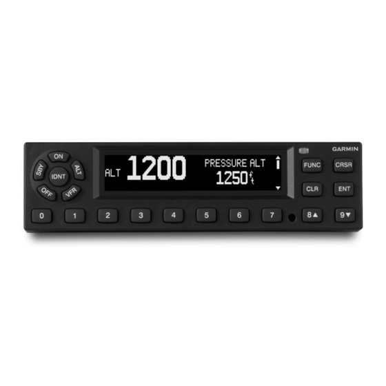
User Manuals: Garmin GTX 335 w GPS ADS-B Transponder
Manuals and User Guides for Garmin GTX 335 w GPS ADS-B Transponder. We have
1
Garmin GTX 335 w GPS ADS-B Transponder manual available for free PDF download: Installation Guidance
Garmin GTX 335 w GPS Installation Guidance (116 pages)
Brand:
Garmin
| Category:
Marine Radio
| Size: 2 MB
Table of Contents
Table of Contents
5
Introduction
10
Terminology
10
Approved Aircraft, Systems, and Equipment
12
Scope
12
Table 1-1 GTX 335 Unit List
12
System Overview
13
Figure 1-1 GTX 335 Interface Summary
14
GTX 335 Interface
14
Figure 1-2 GTX 335 Front Panel
15
Gae
18
Pre-Installation Checklist
19
System Installation
19
Table 1-2 GTX 335 Pre-Installation Checklist
19
Environmental Qualification Form
20
Power Requirements
20
Reference Documentation
20
Table 1-3 Electrical Load
20
Table 1-4 Garmin Documents
20
Table 1-5 Garmin Documents Available Upon Request
20
Technical Specifications
20
STC Permission
21
Table 1-6 Federal Aviation Administration Documents
21
Table 1-7 Industry Standards
21
2 Limitations
22
Operational Limitations
22
Installation Limitations
22
3 Installation Overview
24
Pre-Installation Information
25
Garmin Available Installation Materials
26
Installation Materials Not Supplied
26
Table 3-1 GTX 335 Connector Kit Options
26
Table 3-2 GTX 335 Backplate Assembly Options
26
Table 3-3 GTS 335 Mount Rack Options
26
Table 3-4 GTX 335 Configuration Module
26
Crimping Tools
27
GTX Series Minimum System Configurations
27
Installation Considerations
27
Table 3-5 Recommended Crimping Tools
27
Test Equipment
27
External Sensors, Devices, and Interface Considerations
28
Table 3-6 Altitude Source Options
28
Mutual Suppression Bus
28
Altitude Source (Required)
28
GPS Source
29
Placards/Labels
30
Switches
30
Table 3-7 Version 2 Compliance W/ Multiple ADS-B out Equipment Installation
30
Installation with Other ADS-B out Systems
30
Antenna Considerations
31
Table 3-8 Maximum Db Loss Allowed from Transponder to Antenna
31
Transponder Antenna
31
Transponder Antenna Location
31
Transponder Antenna Installation
31
Table 3-9 Coaxial Cable Specifications
32
Table 3-10 Typical Cable Connector Loss
32
GPS Antenna (GTX 335 with SBAS/GPS)
32
Table 3-11 GTX 335 GPS Antennas
33
GPS Antenna Location
33
Figure 3-1 GPS Antenna Location (GTX 335 with SBAS/GPS)
34
GPS Coaxial Cable Requirements (GTX 335 with SBAS/GPS)
35
Table 3-12 GPS Db Loss Allowance
35
Cable and Wiring Considerations
36
Circuit Protection and Power Distribution
36
Audio Interference
36
Pressurized Aircraft Considerations
37
Shield Termination Considerations
37
General Installation Practices
36
General Electrical Bonding
38
Table 3-13 Ground Plane Definitions and Ground Path Resistance Requirements
39
Figure 3-2 Electrical Bond Preparation - Nut Plate
40
Figure 3-3 Electrical Bond Preparation - Bolt/Nut Joint
40
Figure 3-4 Electrical Bond Preparation - Terminal Lug
40
Aluminum Surface Preparation
40
Bonding Jumper
41
Figure 3-5 Bonding Strap
42
Table 3-14 Airframe Bonding Hardware
42
Transponder Antenna Bonding
42
Figure 3-6 Transponder Antenna Minimum Ground Plane Radius
43
GPS Antenna Bonding
43
Electrical Load Analysis
44
Figure 3-7 GPS/SBAS Antenna Minimum Ground Plane Radius
44
Aircraft Without Existing Electrical Load Analysis
44
Electrical Load Is Decreased after Modification
44
Electrical Load Is Increased after Modification
45
Performing an Electrical Load Analysis by Measurement
45
Figure 3-8 Ammeter Placement for Current Measurements
46
Figure 3-9 GTX Electrical Load Tabulation Form
48
Figure 3-10 GTX Electrical Load Tabulation Form (Sample)
50
Figure 3-11 Battery Capacity Analysis Example
52
Battery Capacity Analysis
52
4 Installation Procedure
53
Structural Installation
53
GTX 335 Panel Mount Installations
54
Figure 4-1 GTX 335 Installation
55
Figure 4-2 Panel Cutout Detail for GTX 335
56
Figure 4-3 Avionics Rack Mounting Rail Considerations
58
General Requirements for Installation in Composite Aircraft
59
Figure 4-4 Fiberglass Insulation for Carbon Fiber Material
60
Figure 4-5 Aluminum Tape Joint
60
Figure 4-6 Grounding to Instrument Panel with Aluminum Tape and Grounding Strap
61
Table 4-1 Instrument Grounding Parts
61
GTX 335 Weight and Balance
62
Table 4-2 Weight of GTX Configurations
62
Table 4-3 Example Weight and Balance Calculation
62
Electrical Installation
63
Wiring (Addition/Change)
63
Special Tools Required
63
Power Distribution
63
Wire and Cable Considerations
63
Coaxial Cable Preparation
63
Wire Harness Construction
63
Shielded Cable Preparation
64
Figure 4-7 Shielded Wire Preparation
65
Table 4-4 Shield Wire Assembly
65
Cable Bundle Termination on Backshell Assembly
66
Connector and Backplate Assembly for GTX 335
67
Figure 4-8 GTX 335 Connector Kit
68
Table 4-5 GTX 335 Connector Kit Hardware
68
Figure 4-9 GTX 3X5 with GPS Backplate Assembly P/N 011-02976-01
69
Table 4-6 Standard Mount Backplate Hardware
69
Figure 4-10 GAE Assembly
70
Gae
70
Figure 4-11 Configuration Module Assembly
71
Table 4-7 Configuration Module Kit, P/N 011-00979-03
71
Configuration Module Installation
71
GAE and Configuration Module Installation
70
GTX Installation
72
GAE Installation
73
AFMS Completion
74
5 Software Update
75
Software Check
76
Figure 5-1 GTX 335 Start-Up Screen
76
Figure 5-2 GTX 335 Product Data Page
76
6 Post Installation Configuration
77
System Configuration Overview
77
Mounting, Wiring, and Power Checks
77
GTX 335 Remote Unit Configuration (Wizard Tool)
78
GTN 6XX/7XX Configuration with GTX
78
Figure 6-1 USB-A and USB-B Connectors
78
GNS 400W/500W Series Configuration
79
7 Operation/Performance Checkout
80
Ground Checks - Interfaces (Configuration Mode)
81
Airborne/Ground Test Mode
81
Audio Panel Interface
81
Ground Checks - Interfaces (Normal Mode)
82
Discrete Switch Interfaces
82
Air Data Interface
82
Temperature Interface GTX 335
83
TIS-A Interface GTX 335
83
Ground Checks - Performance
84
GPS Reception (Internal GPS Receiver)
84
Regulatory Tests
85
ADS-B out Test
85
EMC Check
86
Figure 7-1 Example EMC Source/Victim Matrix
87
Documentation Checks
88
Airplane Flight Manual Supplement
88
Configuration and Checkout Log
88
Instructions for Continued Airworthiness
88
8 Connector Pinout
89
Figure 8-1 Rear View, Connector J3251
89
Gtx 335
89
Table 8-1 GTX 335 J3251 Pin Assignments
90
Table 8-2 Lighting/Power Pin Assignments
92
Table 8-3 GTX 335 Power Control Inputs
92
GTX 335 Power and Lighting Inputs
92
GTX 335 Power Control Input
92
GTX 335 Encoded Altitude Inputs
92
Table 8-4 GTX 335 Encoded Altitude Inputs
93
Table 8-5 GTX 335 Discrete Outputs
94
Table 8-6 GTX 335 Discrete Inputs
94
GTX 335 Discrete Outputs
94
GTX 335 Discrete Inputs
94
Gtx
94
Appendixa Mechanical Drawings
95
Figure A-1 GTX 335 Panel Mount Dimensions and Center of Gravity
95
Figure A-2 GTX 3X5 Panel Mount Rack Assembly
96
Figure A-3 GTX 335 Connector and Vent Location
97
Figure A-4 Optional Altitude Sensor
97
Appendixb Interconnect Drawings
98
Figure B-1 GTX 335 - Power, Ground, and Configuration Module Interconnect
100
Figure B-2 GTX 335 Switches Interconnect
102
Figure B-3 GTX 335 - GNS 400W/500W Series Interconnect
103
Figure B-4 GTX 335 - GTN 6XX/7XX Interconnect
104
Figure B-5 GTX 335 - Altitude Data Source Interconnect
106
Figure B-6 GTX 335 - Audio Interconnect
107
Figure B-7 GTX 335 - GTS 8XX
108
Appendixc Equipment Compatibility and Configuration
109
Altitude Source
109
TIS-A Traffic Display
109
Garmin GTS Traffic Interface Configuration
109
Audio Panels
112
Appendixd Acceptable Hardware
114
Table D-1 Screws
114
Table D-2 Washer
114
Table D-3 Nuts
115
Table D-4 Nutplates
115
Table D-5 Clipnut
115
Table D-6 Rivets
115
Table D-7 Rivets, Blind
115
Advertisement
Advertisement
Related Products
Garmin GTX 330
Garmin GTX 335 Series
Garmin GTX 335
Garmin GTX 335R w/GPS
Garmin GTX 33
Garmin GTX 335 NV
Garmin GTX 335 w/GPS
Garmin GTX 333
Garmin GTX-33ES
Garmin GTX 330ES
Garmin Categories
GPS
Watch
Car Navigation system
Avionics Display
Marine Equipment
More Garmin Manuals
Login
Sign In
OR
Sign in with Facebook
Sign in with Google
Upload manual
Upload from disk
Upload from URL