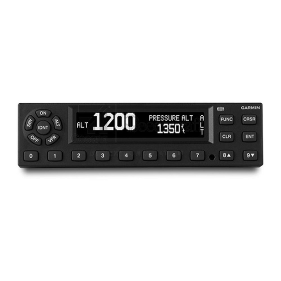
Page 1
This drawing and the specifications contained herein are c/o Garmin International, Inc. the property of Garmin Ltd. or its subsidiaries and may not be reproduced or used in whole or in part as the basis 1 2 0 0 E . 1 5 1 s t S t .
Page 3
Garmin. Garmin hereby grants permission to download a single copy of this manual and of any revision to this manual onto a hard drive or other electronic storage medium to be viewed and to...
Page 4
California to cause cancer, birth defects, or reproductive harm. This notice is provided in accordance with California's Proposition 65. If you have any questions or would like additional information, please refer to Garmin’s website, www.garmin.com/prop65. WARNING Perchlorate Material – special handling may apply.
Garmin recommends installation of the GTX 3x5 by a Garmin–authorized installer. To the extent allowable by law, Garmin will not be liable for damages resulting from improper or negligent installation of the GTX 3x5. For questions, contact Garmin Aviation Product Support at 1-888-606-5482.
Page 10
• Flight timers • Audio output • Interface to Garmin display products such as the GTN and GNS series • Bluetooth interface for display of weather and traffic on portable devices (GTX 345) • Reception of TIS-A traffic (GTX 335)
Definitions and Abbreviations Definitions Except where specifically noted, references made to GTX 3x5 will equally apply to all GTX 3x5 variants. Abbreviations The following abbreviations/acronyms are used within this document: Advisory Circular Automatic Direction Finder ADS-B Automatic Dependent Surveillance-Broadcast ADS-R Automatic Dependent Surveillance-Rebroadcast AFMS Aircraft Flight Manual Supplement...
Advisory traffic information is available to aircraft equipped with a Mode S data link such as the Garmin GTX 335 or GTX 345. Advisory traffic information may be displayed on a Garmin 400W/500W Series unit.
General Specifications 1.7.1 It is the responsibility of the installing agency to obtain the latest revision of the GTX 3x5 EQF. To obtain a copy of the EQF, see Garmin’s Dealer Resource Center. Table 1-3 Physical Characteristics - Panel Mount Units...
3.10 lb (1.41 kg) backplate, and connectors) -4°F to 131°F (-20°C to + 55°C) For more details refer to the environmental qualification form at Operating temperature range Garmin’s Dealer Resource Center. See section section 1.7.1 for form part number. Altitude range...
Antenna performance is critical to GNSS receiver operation. Antennas listed in table 1-10 meet specifications outlined in Antenna Minimum Performance Specification for Garmin’s GPS/WAAS Receiver System. To achieve acceptable performance with the GTX 335 or GTX 345 with internal GNSS receiver, antennas listed table 1-10 must be used.
1.13 Power Specifications Table 1-11 Power Specifications Unit Characteristic Specification All units Input voltage 9 to 33 Vdc 14 Vdc 28 Vdc GTX 325 Power input __ W typical, __ W max Input current, typical Input current, maximum GTX 335 Power input 8 W typical, 15 W maximum Input current, typical...
1.14 Certification The GTX 3x5 meets compliance with the claimed TSO(s) when interfaced with the equipment defined in this manual, and installed in accordance with the requirements and limitations as defined. The Appliance Project Identifier (API) for the GTX 3x5 is GMN-01216. The API is used for project identification with the FAA and EASA.
Table 1-14 TSO/ETSO Deviations TSO/ETSO Deviation 1. Garmin requests a deviation from the mentioned TSOs to use RTCA DO-160G instead of earlier versions of RTCA/DO-160 as the standard for Environmental Conditions and TSO-C74d Test Procedures for Airborne Equipment. ELOS is provided by use of later revision requirement document.
Page 22
TSO/ETSO Deviation 1. Garmin requests a deviation from the mentioned TSOs for marking the TSO number, Type/Class and Date of Manufacture, Deviation and Software Part Number on the exterior of the unit. Instead, Garmin requests to include product name, part number, serial number, and this statement on the unit’s nameplate label “TSO-C112e See IM for...
Page 23
See Order 8150.1C Section 7-4e-4 and 8110.49 for further supporting statement of policy. 2. Garmin requests a deviation from the TSO-C166b not to process ADS-R as required by RTCA/DO-260B section 2.2.18. The GMN-01216 has a built-in UAT Datalink receiver and will have access to transmitted UAT data that are present in ADS-R broadcast.
1.14.2 Design Assurance Levels Table 1-15 Software Design Assurance Levels DO-178B System Function Level Transponder (mode S, ATCRBS) Mode S extended squitter output Mode S extended squitter reception UAT reception Correlation of traffic (ADS-B, ADS-R, TIS-B, and TAS/TCAS) Traffic processing and output to display Flight information data (FIS-B) data processing and output to display Internal GNSS receiver (with internal GPS) HSDB data forwarding...
CAUTION The UHF transmitter in this equipment is guaranteed to meet Federal Communications Commission acceptance over the operating temperature range. Modifications not expressly approved by Garmin could invalidate the license and make it unlawful to operate the equipment. NOTE For non-US installations consult the local spectrum management agency for requirements.
2 LIMITATIONS This article meets the minimum performance and quality control standards required by a TSO. Installation of this article requires separate approval. 2.1 HSDB Packet Forwarding The GTX 345 HSDB is not approved for forwarding data whose failure condition or loss of malfunction is classified as hazardous or catastrophic.
3 INSTALLATION OVERVIEW 3.1 Introduction Equipment information for installing the GTX 3x5 and related optional accessories is provided in this section. Installation of the GTX 3x5 should follow the information detailed in this manual and airworthiness approved data. Cabling is fabricated by the installing agency to fit each particular aircraft. Always follow acceptable avionics installation practices as outlined in AC 43.13-1B and AC 43.13-2B or later FAA approved revisions.
3.4.4 GA 36 Antenna Antenna includes four 10-32 UNF-2A x 1.00" SS 303 mounting screws and one O-ring. An antenna doubler may also be required. Refer to appropriate antenna installation data. To secure the antenna, four #10 washers and four #10 self-locking nuts are required. Suitable nut plates may be secured to the doubler.
3.8 Antenna Considerations Mounting location considerations for the antenna(s) is provided in this section. The recommended antenna placements are illustrated in figure 3-1. 3.8.1 Transponder Antenna NOTE For installations on composite aircraft, ground planes must be considered. Conductive wire mesh, radials, or thin aluminum sheets embedded in the composite material provide the ground plane allowing the antenna pattern (gain) to be maximized for improved transponder performance.
Page 34
(ex. GPS and COM, GPS and XM) provided the combination antenna is TSO authorized and has been tested to meet Garmin’s minimum performance standards. See table 1-10 for approved antennas.
ANTENNA MASKED BY VERTICAL FIN, T-TAIL, OR DORSAL FIN. ANTENNA NOT MOUNTED LEVEL WITH RESPECT TO THE NORMAL FLIGHT ATTITUDE. DISTANCE BETWEEN COM AND GPS ANTENNAS SHOULD BE GREATER THAN TWO FEET. GOOD BETTER GREATER THAN THREE INCHES OF WINDSCREEN NORMAL FLIGHT ATTITUDE...
3.10 Cabling and Wiring Wiring should be installed in accordance with AC 43.13-1B Chapter 11, Sections 8 through 13. The following issues should be addressed: • It should not be possible for the cable harness to be exposed to wire chafing. •...
4 INSTALLATION PROCEDURE 4.1 Wiring Harness Installation All electrical connections, except for the antenna(s) and shield grounds, are made through the D-sub connectors on the rear of the unit. The shield grounds are terminated to the connector backshells. The rear connector pinout and descriptions for the interface connections are included in section 5. See appendix ?? for wiring diagrams.
heads or other obstructions prevent the unit from fully engaging in the rack, see section 6.3. Exercise caution when installing the rack in the instrument panel. Deformation of the rack may make it difficult to install and remove the GTX 3x5. 2.
5 CONNECTOR PINOUT INFORMATION 5.1 Main Board Connector - P3251 This section describes the main board connector, which is available on all unit configurations. Pin Name CONFIG CLOCK USB D+ OAT INPUT 1PPS A ARINC 429 TXA ARINC 329 TXB RS-232 #3 TxD RS-232 #2 TxD RS-232 #1 TxD...
Page 40
Pin Name ARINC 429 RX1A ARINC 429 RX1B RS-232 #3 RxD RS-232 #2 RxD RS-232 #1 RxD ALT A2 ALT B2 ALT C2 TEST MODE EXT IDENT AUDIO MUTE PWR CONTROL SW PWR OUT LTNG LO GROUND (power ground) AV PWR 1 CONFIG PWR USB V+ GROUND (USB ground)
5.2 ADS-B Board Connector – P3252 This section describes the ADS-B In board connector, which is available on only the GTX 345 configurations. Pin Name HSDB 1 TX B HSDB 1 RX B HSDB 2 TX B HSDB 2 RX B RS-232 #4 TxD HSDB 1 TX A HSDB 1 RX A...
The SW PWR OUT is a switched power output source, typically used for powering devices such as a remote altitude encoder. The SW PWR OUT is active when the GTX 3x5 power is on, and is rated for 1A max. The KEEP ALIVE input is used to maintain the GPS real time clock.
The GTX 3x5 can use pressure altitude inputs from several different sources, using the gray code inputs, an RS-232 serial input, an ARINC 429 input, or the optional pressure sensor module (Garmin P/N 011- 03080-00). If multiple altitude sources are connected, the GTX 3x5 will prioritize them as follows: 1.
5.6.2 Altitude Gray Code Input The parallel Gray code input can be used as a pressure altitude input. Pin Name Connector ALT A1 P3251 ALT A2 P3251 ALT A4 P3251 ALT B1 P3251 ALT B2 P3251 ALT B4 P3251 ALT C1 P3251 ALT C2 P3251...
Page 45
5.7.1 EXT STANDBY When the EXT STANDBY input is pulled low, the GTX 3x5 is put in standby and will not transmit. This input is typically used when installing two transponders, with a selector switch connected to select the active transponder. 5.7.2 TEST MODE The TEST MODE input is reserved for use at the factory and should not be connected in the aircraft...
5.11 Audio Output Pin Name Connector AUDIO OUT P3251 GROUND (audio ground) P3251 The audio output is used to provide aural traffic alerts. The output is capable of 100mW into a 500Ω load. 5.12 1PPS Interface Pin Name Connector 1PPS A P3251 1PPS B P3251...
5.14 USB Interface The USB interface is intended only for unit configuration, software updates, and service while the aircraft is on the ground. It is not intended for use during normal operation or when airborne. Pin Name Connector USB D+ P3251 USB D- P3251...
6 POST INSTALLATION CONFIGURATION AND CHECKOUT 6.1 System Configuration Overview Checkout and configuration instruction for the GTX 3x5 is provided in this section. • Perform the installation checks • Configure the GTX 3x5 for the specific installation • Perform ground checks to verify interfaces to external equipment •...
Page 51
running on a PC. GTX 3x5 panel mount units may also be configured using the program. See section 4.3 for configuration using the remote interface. This section provides the configuration instructions for a panel mount unit. For remote configuration, see Section 4.3.
6.4.5 RS-422 Selection Description 6.4.6 HSDB 6.4.7 Pressure Sensor Correspondence The optional pressure sensor module requires a correspondence adjustment to match the aircraft primary altitude display. 6.5 Remote Unit Configuration 6.6 Diagnostic Information 6.7 Ground Checks 6.7.1 Interface Checkout 6.7.2 GPS Reception The GPS checks described in this section are applicable to GTX 335 and GTX 345 units with the internal GPS receiver.
121.185MHz 130.285MHz 121.190MHz 131.290MHz 7. Repeat steps 2 through 5 for all remaining com transceivers in the aircraft. 8. If the aircraft is TCAS equipped, turn on the TCAS system and verify that the GPS position remains valid. 9. If he aircraft is SATCOM equipped, use the SATCOM system and verify that the GPS position remains valid.
7 CONTINUED AIRWORTHINESS Other than for regulatory periodic functional checks, maintenance of the GTX 3x5 is “on condition” only. Periodic maintenance of the GTX 3x5 is not required. 190-01499-02 GTX 3x5 TSO Installation Manual Rev. 1 Page 7-1...
APPENDIX A MECHANICAL DRAWINGS A.1 Drawing List The following drawings are included in this section. □ Figure A-1 GTX 3x5 Panel Mount Assembly □ Figure A-2 GTX 3x5 Panel Mount Dimensions and CG □ Figure A-3 GTX 3x5 Horizontal Remote Mount Assembly □...
Page 65
1P603 P3251 No. 1 GIA 63W GTX 3x5 [R] MODE S TRANSPONDER MAIN RS-232 IN 5 SIGNAL GROUND MAIN RS-232 OUT 5 RS-232 OUT 1 SIGNAL GROUND RS-232 IN 1 2P603 No. 2 GIA 63W MAIN RS-232 IN 5 RS-232 OUT 2 SIGNAL GROUND SIGNAL GROUND MAIN RS-232 OUT 5...
Page 67
Part Information GPN: 190-01499-02 Description: GTX3x5 Transponder TSO Installation Manual Part Type: Manuals / Printed Literature Lifecycle Phase: Experimental Rev: IR#068314 Item Attribution Document Review Required: Item Notes: Preferred Rating: ESD Sensitive: Moisture Sensitive: Limited Shelf Life: Magnetic Sensitive: Item Attribution 1 of 1 Item: 190-01499-02 Rev:1 IR#068314 Creation Date: 12-May-2015 03:29 PM CST...
Need help?
Do you have a question about the GTX 3x5 Series and is the answer not in the manual?
Questions and answers