Advertisement
Quick Links
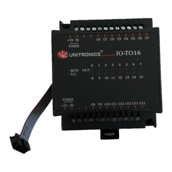
IO-TO16
The IO-TO16 is an I/O expansion module
that can be used in conjunction with
specific Unitronics OPLC controllers.
The module offers 16 pnp (source)
transistor outputs.
The interface between the module and
the OPLC is provided by an adapter.
The module may either be snap-mounted
on a DIN rail, or screw-mounted onto a
mounting plate.
Component identification
1
Module-to-module connector
2
Status indicators
3
Outputs' power supply connection
points for each group of outputs
4
Output connection points: O8-O15
5
Output status indicators
6
Module-to-module connector port
7
Output connection points: O0-O7
User safety and equipment protection guidelines
This document is intended to aid trained and competent personnel in the installation of this equipment as defined
by the European directives for machinery, low voltage and EMC. Only a technician or engineer trained in the
local and national electrical standards should perform tasks associated with the electrical wiring of this device.
Under no circumstances will Unitronics be liable or responsible for any consequential damage that may
arise as a result of installation or use of this equipment, and is not responsible for problems resulting from
improper or irresponsible use of this device.
All examples and diagrams shown in the manual are intended to aid understanding. They do not
guarantee operation.
Unitronics accepts no responsibility for actual use of this product based on these examples.
Only qualified service personnel should open this device or carry out repairs.
Please dispose of this product in accordance with local and national standards and regulations.
Check the user program before running it.
Do not attempt to use this device with voltage exceeding permissible levels.
Install an external circuit breaker and take all appropriate safety measures against short-
circuiting in external wiring.
Failure to comply with appropriate safety guidelines can result in severe personal injury or
property damage. Always exercise proper caution when working with electrical equipment.
Unitronics Industrial Automation Systems
I/O Expansion Module
1
2
www.klinkmann.com
16 Transistor Outputs
3
3
5 / 2011
7
6
5
4
1
Advertisement

Subscribe to Our Youtube Channel
Related Manuals for Unitronics IO-TO16


Summary of Contents for Unitronics IO-TO16
- Page 1 Under no circumstances will Unitronics be liable or responsible for any consequential damage that may arise as a result of installation or use of this equipment, and is not responsible for problems resulting from improper or irresponsible use of this device.
-
Page 2: Mounting The Module
Snap the device onto the DIN rail as shown below; the module will be squarely situated on the DIN rail. 80mm Screw-Mounting The figure on the next page is drawn to scale. It may be used as a guide for screw-mounting the module. Mounting screw type: either M3 or NC6-32. Unitronics Industrial Automation Systems... - Page 3 5 / 2011 www.klinkmann.com IO-T O16 1 1 / 0 0 I / O E x p a n s i o n M o d u l e 80mm 68.4mm 5.8mm 4mm (x2) Unitronics Industrial Automation Systems...
-
Page 4: Connecting Expansion Modules
Input or output cables should not be run through the same multi-core cable or share the same wire. Allow for voltage drop and noise interference with output lines used over an extended distance. Use wire that is properly sized for the load. Unitronics Industrial Automation Systems... - Page 5 In the event of voltage fluctuations or non-conformity to voltage power supply specifications, connect the device to a regulated power supply. 24VDC power supply for 1st group of outputs Circuit Load Protection Device Circuit Protection Load Device 24VDC power supply for 2nd group of outputs Unitronics Industrial Automation Systems...
- Page 6 IO - T O 16 I / O E x p a n s i o n M o d u l e 1 1 / 0 0 IO-TO16 Technical Specifications Max. current consumption 50mA maximum from the adapter’s 5VDC 0.12W @ 5VDC...
- Page 7 RO8 is always assigned the number 7. Its I/Os are addressed accordingly. Example Input #5, located on an EX90-DI8-RO8 connected to an M90 OPLC will be addressed as I 149, 149 = 32 + 7 • 16 + 5 Unitronics Industrial Automation Systems...
- Page 8 * Stand-alone module. Other modules are used in conjunction with the EX-A1 adapter To order the expansion module that best fits your system, contact your local distributor. For a list of Unitronics distributors, check our website: http://www.unitronic.com/contact.htm Unitronics_IO-TO16_IO_Expansion_en_0511.pdf Helsinki St.
Need help?
Do you have a question about the IO-TO16 and is the answer not in the manual?
Questions and answers