Table of Contents
Advertisement
Quick Links
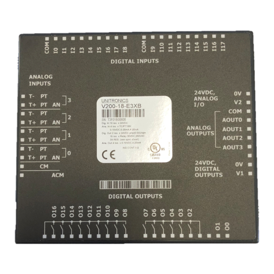
V200-18-E3B
The V200-18-E3B
plugs directly into the
back of compatible
Unitronics OPLCs,
creating a self-
contained PLC unit
with a local I/O
configuration.
Before using this product, it is the responsibility of the user to read and understand this document
and any accompanying documentation.
All examples and diagrams shown herein are intended to aid understanding, and do not guarantee
operation. Unitronics accepts no responsibility for actual use of this product based on these
examples.
Please dispose of this product in accordance with local and national standards and regulations.
Only qualified service personnel should open this device or carry out repairs.
User safety and equipment protection guidelines
This document is intended to aid trained and competent personnel in the installation of this equipment as
defined by the European directives for machinery, low voltage, and EMC. Only a technician or engineer trained
in the local and national electrical standards should perform tasks associated with the device's electrical wiring.
Symbols are used to highlight
information relating to the user's
personal safety and equipment
protection throughout this document.
When these symbols appear, the
associated information must be read
carefully and understood fully.
Failure to comply with appropriate safety guidelines can result in severe personal injury
or property damage. Always exercise proper caution when working with electrical
equipment.
Check the user program before running it.
Do not attempt to use this device with parameters that exceed permissible levels.
Install an external circuit breaker and take appropriate safety measures against short-
circuiting in external wiring.
To avoid damaging the system, do not connect / disconnect the device when the power
is on.
Caution
Ascertain that terminal blocks are properly secured in place.
Environmental Considerations
Do not install in areas with: excessive or conductive dust, corrosive or flammable gas,
moisture or rain, excessive heat, regular impact shocks or excessive vibration.
Provide proper ventilation by leaving at least 10mm of space between the top and
bottom edges of the device and the enclosure walls.
Do not place in water or let water leak onto the unit.
Do not allow debris to fall inside the unit during installation.
Unitronics Industrial Automation
Snap-in I/O Module
Features
18 isolated digital inputs, includes 2 H.S.C inputs, type pnp/npn
(source/sink)
15 isolated relay outputs
2 isolated pnp/npn (source/sink) transistor outputs, includes 2 H.S. outputs
4 isolated analog/PT100/TC inputs
4 isolated analog outputs
Symbol
Caution
Meaning
Description
The identified danger causes physical
Danger
and property damage.
The identified danger can cause
Warning
physical and property damage.
Caution
Use caution.
1
Advertisement
Table of Contents

Related Manuals for Unitronics V200-18-E3B


Summary of Contents for Unitronics V200-18-E3B
- Page 1 All examples and diagrams shown herein are intended to aid understanding, and do not guarantee operation. Unitronics accepts no responsibility for actual use of this product based on these examples. Please dispose of this product in accordance with local and national standards and regulations.
-
Page 2: Wiring Procedures
Inputs I0 and I2 can be used as normal digital inputs, as high-speed counters, or as part of a shaft encoder. Inputs I1 and I3 can be used as normal digital inputs, as high-speed counter resets, or as part of a shaft encoder. Unitronics Industrial Automation... - Page 3 (source) digital input wiring npn (sink) high-speed counter pnp (source) high-speed counter Inputs I0, I1, and I2, I3 can be used as shaft encoders as shown below. npn (sink) shaft encoder wiring pnp (source) shaft encoder wiring Unitronics Industrial Automation...
-
Page 4: Relay Outputs
To increase the life span of the relay output contacts and protect the device from potential damage by reverse EMF, connect: a clamping diode in parallel with each inductive DC load, an RC snubber circuit in parallel with each inductive AC load. Unitronics Industrial Automation... -
Page 5: Transistor Outputs
Since the analog I/O power supply is isolated, the controller’s 24VDC power supply may also be used to power the analog I/Os. The 24VDC power supply must be turned on and off simultaneously with the controller’s power supply. Unitronics Industrial Automation... -
Page 6: Analog Inputs
Wire one lead of each thermocouple input to the common signal (CM) as shown below. Wire the CM to the ACM signal as shown below, using a single wire, not exceeding 2 cm in length. 4 wire PT100 can be used by leaving one of the sensor leads unconnected. PT100 Unitronics Industrial Automation... -
Page 7: Thermocouple Inputs
- Use the appropriate wiring as shown below. - Open the device and set the jumpers according to the instructions beginning on page 8. To ensure proper performance, a warm-up period of a half an hour is recommended. current/voltage Unitronics Industrial Automation... -
Page 8: Changing Jumper Settings
PCB board. Do not remove any other screws. 4. Holding the PCB board by its edges, gently lift it out of the module. Unitronics Industrial Automation... - Page 9 PT100 Analog input 3 Analog input 2 Bottom PCB board Analog input 1 Analog input 0 Digital Output Jumpers Jumper # PNP* Note that Jumpers #15 & Digital Output 0 16 are not used Digital Output 1 Unitronics Industrial Automation...
- Page 10 Next, reinstall the module. Line the circular guidelines on the controller up with the guidelines on the Snap-in I/O Module as shown below. Apply even pressure on all 4 corners until you hear a distinct ‘click’. The module is now installed. Check that all sides and corners are correctly aligned. Unitronics Industrial Automation...
- Page 11 1 1 / 0 4 V 2 0 0 - 1 8 - E 3 B S n a p - i n I / O M o d u l e V200-18-E3B Technical Specifications Digital Inputs Number of inputs...
- Page 12 See Digital Output’s Power Supply above npn (sink) power supply operating voltage 3.5V to 28.8VDC, unrelated to the voltage of either the I/O module or the controller Notes: Both transistor outputs may be used as high-speed outputs. Unitronics Industrial Automation...
- Page 13 Yes. See Note 6 Notes: The analog value can indicate faults as shown below: Value Possible Cause 4096 Input value deviates slightly above the input range 32767 -Input value deviates greatly above or below the input range -Power supply disconnected Unitronics Industrial Automation...
- Page 14 ½ hour typically, ±1°C/±1.8°F repeatability Status indication Notes: The device can also measure voltage within the range of -5 to 56mV, at a resolution of 0.01mV. The device can also measure raw value frequency at a resolution of 14-bits(16384) Unitronics Industrial Automation...
- Page 15 Environmental IP20 / NEMA1 Operating temperature 0° to 45°C (32° to 113°F) Storage temperature -20° to 60° C (-4° to 140°F) Relative Humidity (RH) 5% to 90% (non-condensing) Dimensions (WxHxD) 138x23x123mm (5.43x0.9x4.84”) Weight 222g (7.83 oz) Unitronics Industrial Automation...
- Page 16 Unitronics assumes no responsibility for the results, direct and/or indirect, of any misuse of the information appearing in this document nor for any use of the Unitronics products referred to herein in any manner deviating from the recommendations made in this document.
Need help?
Do you have a question about the V200-18-E3B and is the answer not in the manual?
Questions and answers