GEA F Series Assembly Instructions Manual

GEA F Series Assembly Instructions Manual

Bock compressors

Advertisement

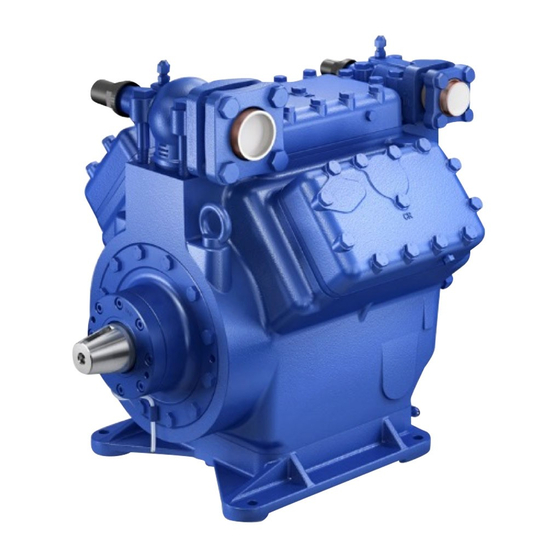
Bock Compressors F/F-NH

Assembly instructions

F2, F3
F4, F5
F14/1166, F14/1366
F16/1751, F16/2051
FX2, FX3
FX4, FX5
FX14/1166, FX14/1366
FX16/1751, FX16/2051
engineering for a better world
3
F2 NH 3 , F3 NH 3
F4 NH 3 , F5 NH 3
F14/1166 NH 3 , F14/1366 NH 3
F16/1751 NH 3 , F16/2051 NH 3
GEA Refrigeration Technologies
D
GB
F
E
1

Advertisement

Table of Contents
loading

Summary of Contents for GEA F Series

  • Page 1: Assembly Instructions

    F4 NH 3 , F5 NH 3 F14/1166, F14/1366 F14/1166 NH 3 , F14/1366 NH 3 F16/1751, F16/2051 F16/1751 NH 3 , F16/2051 NH 3 FX2, FX3 FX4, FX5 FX14/1166, FX14/1366 FX16/1751, FX16/2051 engineering for a better world GEA Refrigeration Technologies...
  • Page 2 Observe the safety instructions contained in these instructions. These instructions must be passed onto the end customer along with the unit in which the compres- sor is installed. Manufacturer GEA Bock GmbH 72636 Frickenhausen Contact GEA Bock GmbH Benzstraße 7...
  • Page 3: Table Of Contents

    Contents Page Safety 1.1 Identification of safety instructions 1.2 Qualifications required of personnel 1.3 General safety instructions 1.4 Additional safety instructions NH 1.5 Intended use Product description 2.1 Short description 2.2 Name plate 2.3 Type code Areas of application F 3.1 Refrigerants F, F-NH 3.2 Oil charge 3.3 Operating limits...
  • Page 4: Safety

    1 | Safety 1.1 Identification of safety instructions: Indicates a dangerous situation which, if not avoided, DANGER! will cause immediate fatal or serious injury. Indicates a dangerous situation which, if not avoided, WARNING! may cause fatal or serious injury. Indicates a dangerous situation which, if not avoided, CAUTION! may cause fairly severe or minor injury.
  • Page 5: General Safety Instructions

    1 | Safety 1.3 General safety instructions DANGER! • Refrigerating compressors are pressurised machines and as such call for heightened caution and care in handling. The maximum permissible overpressure must not be exceeded, even for testing purposes. WARNING! • Risk of burns! Depending on the operating conditions, surface temperatures of over 60°C on the discharge side or below 0°C on the suction side can be reached.
  • Page 6: Product Description

    2 | Product description 2.1 Short description Open type compressors for external drive (V-belt or coupling) with oil pump lubrication Short description NH Based on the F compressor series, a specially modified selection of compressors is available for use with the refrigerant R 717. Important differences from the basic compressor F: Pistons with three-ring assembly Con-rod with additional oil supply oil to the small end...
  • Page 7: Name Plate

    2 | Product description F4, F5 Discharge shut-off valve Cylinder cover Suction shut-off valve Valve plate Shaft seal Shaft end Compressor housing Name plate Base plate Fig. 2 F14, F16 Discharge shut-off valve Suction shut-off valve Transport eyelet Cylinder cover Transport eyelet Valve plate Shaft seal...
  • Page 8: Type Code

    2 | Product description 2.2 Name plate (example) GEA Bock GmbH 72636 Frickenhausen, Germany FX16/2051 19/28 SE55 Fig. 4 Type designation Machine number Rotation speed minimum with a corresponding displacement Rotation speed maximum with a corresponding displacement ND(LP): Max. admissible operating pressure Suction side Observe the limit of HD(HP): Max.
  • Page 9 3 | Areas of application F, F-NH 3.1 Refrigerants • HFKW: R134a, R404A/R507, R407C • (H)FCKW: R717 3.2 Oil charge The compressors are filled with the following oil type at the factory: - for R134a, R404A/R507, R407C FUCHS Reniso Triton SE 55 - for R22 FUCHS Reniso SP 46 Compressors with ester oil charge (FUCHS Reniso Triton SE 55) are marked with an X in the type...
  • Page 10: Areas Of Application F

    3| Areas of application F 3.3 Operating limits R134a Unlimited application range Fig. 6 Reduced suction gas temperature Evaporating temperature (°C) Condensing temperature (°C) R404A/R507 Suction gas superheat (K) Suction gas temperature (°C) Permissible rotation speeds: F2, F3: 960 - 1800 rpm Fig.
  • Page 11: Areas Of Application F-Nh

    4| Areas of application F-NH 4.1 Oil charge NH The compressors are filled with the following oil type at the factory: - for R717: Fuchs Reniso KC 68 4.2 Operating limits NH t (°C) Unlimited application range Supplementary cooling necessary (e.g. water-cooled cylinder covers) Evaporating temperature (°C) Condensing temperature (°C)
  • Page 12: Compressor Assembly

    5| Compressor assembly INFO! New compressors are factory-filled with inert gas (3 bar nitrogen). Leave this service charge in the compressor for as long as possible and prevent the ingress of air. Check the compressor for transport damage before starting any work.
  • Page 13: Maximum Permissible Inclination

    5| Compressor assembly 5.2 Maximum permissible inclination ATTENTION! Poor lubrication can damage the compressor. Respect the stated values. max. 30°, max. 2 minutes max. 15°, continuous operation Fig. 16 5.3 Pipe connections ATTENTION! Overheating can damage the valve. Remove the pipe supports from the valve for soldering. Only solder using inert gas to inhibit oxidation products (scale).
  • Page 14: Laying Suction And Discharge Lines

    5| Compressor assembly 5.5 Laying suction and discharge lines INFO! Proper layout of the suction and discharge lines directly after the compressor is integral to the system’s smooth running and vibration behaviour. ATTENTION! Improperly installed pipes can cause cracks and tears, the result being a loss of refrigerant.
  • Page 15: Operating Mode Of The Lockable Service Connections

    5| Compressor assembly 5.7 Operating mode of the lockable service connections Service connection closed Connection Pipe connection Spindle blocked Fig. 21 Opening the shut-off valve: Spindle: turn to the left (counter-clockwise) as far as it will go. —> The shut-off valve is then fully open and the service connection is closed. The connection which is not lockable is provided for safety devices.
  • Page 16: Drive

    CAUTION! Mount suitable safeguards when driving the compressor by means of V-belts or shaft couplings! The compressors of the F series can be driven by V-belts or directly by shaft couplings. V-belt: Proper assembly of belt drive: - The pulleys of compressor and drive motor must be firmly mounted and in line.
  • Page 17: Oil Sump Heating (Standard By F4, F5, F14 And F16)

    5| Compressor assembly 5.9 Oil sump heating When the compressor is at a standstill, refrigerant diffuses into the lubrication oil of the compressor housing, depending on pressure and ambient temperature. This reduces the lubrication capacity of the oil. When the compressor starts up, the refrigerant contained in the oil evaporates out through the reduction in pressure.
  • Page 18: Preparations For Start-Up

    6| Commissioning 6.1 Preparations for start-up INFO! To protect the compressor against inadmissible operating conditions, high pressure and low pressure pressostats are mandatory on the installation side. The compressor has undergone trials in the factory and all functions have been tested. There are therefore no special running-in instructions.
  • Page 19: Refrigerant Charge

    6| Commissioning 6.5 Refrigerant charge CAUTION! Wear personal protective clothing such as goggles and protective gloves! Make sure that the suction and discharge line valves are open. With the compressor switched off, add the liquid refrigerant directly to the condenser or receiver, breaking the vacuum.
  • Page 20: Shaft Seal Change

    6| Commissioning 6.7 Shaft seal change As changing the shaft seal involves opening the refrigerant circuit, this is recommended only if the seal is losing refrigerant. Replacing the shaft seal is described in the spare part kit concerned. 6.8 Start-up WARNING! Ensure that both shut-off valves are open before starting the compressor! Check that the safety and protection devices (pressure switch, motor protection, electrical...
  • Page 21: Maintenance

    7| Maintenance 7.1 Preparation WARNING! Before starting any work on the compressor: Switch off the compressor and secure it to prevent a restart. Relieve compressor of system pressure. Prevent air from infiltrating the system! After maintenance has been performed: Connect safety switch. Evacuate compressor.
  • Page 22: Spare Parts Recommendation Nh

    7| Maintenance 7.4 Spare parts recommendation NH F14/1166 NH F16/1751 NH Type F2 NH F3 NH F4 NH F5 NH F14/1366 NH F16/2051 NH Ref. No. Designation Set gaskets 08069 08070 08071 08072 08492 08493 Shaft seal 08001 08001 08008 08008 08444 08012 Valve plate set NH...
  • Page 23: Technical Data

    8| Technical data F2 - F16...
  • Page 24: Technical Data F2 Nh -F16 Nh

    9| Technical data F2-NH - F16-NH...
  • Page 25: Dimensions And Connections F

    10| Dimensions and connections F Compressor type F2 H/D1 4xØ9 ca.255 Fig. 23 Dimensions in mm Shaft end F2 Woodruff key Cone Fig. 24 Dimensions in mm Dimensions for view X see page 32...
  • Page 26 10| Dimensions and connections F Compressor type F3 D/D1/H 4xØ9 96.5 ca.315 Fig. 25 Dimensions in mm Shaft end F3 Woodruff key Cone Fig. 26 Dimensions in mm Dimensions for view X see page 32...
  • Page 27 10| Dimensions and connections F Compressor type F4 ca.305 B DV ca.225 ca.455 Fig. 27 Dimensions in mm Shaft end F4 Woodruff key Cone Fig. 28 Dimensions in mm Dimensions for view X see page 32...
  • Page 28 10| Dimensions and connections F Compressor type F5 ca.355 4xØ11 ca.470 Fig. 29 Dimensions in mm Shaft end F5 Woodruff key Cone Fig. 30 Dimensions in mm Dimensions for view X see page 32...
  • Page 29 10| Dimensions and connections F Compressor type F14 F14/1166 F14/1366 ca.415 121.5 4xØ13.5 ÖV1 ca.530 Fig. 31 Dimensions in mm Dimensions in () = with elevated base plate Shaft end F14 Woodruff key Cone Leak oil Fig. 32 drain hose Dimensions in mm Dimensions for view X, Y see page 32...
  • Page 30 10| Dimensions and connections F Compressor type F16 F16/1751 F16/2051 ca.515 143.5 13.5 ÖV1 ca.580 Fig. 33 Dimensions in mm Dimensions in () = with elevated base plate Shaft end F16 Woodruff key Cone Leak oil Fig. 34 drain hose Dimensions in mm Dimensions for view X, Y see page 32...
  • Page 31 10| Dimensions and connections F...
  • Page 32 10| Dimensions and connections 10.1 View X, Y • Oil sight glass • Connection facility for parallel operation Position view X: Position view Y: F2, F3, F4, F5, F14, F16 F14, F16 4 hole oil sight glass Second oil sight glass can be attached as an option (available as original equipment only) 90°...
  • Page 33: Dimensions And Connections F-Nh

    11| Dimensions and connections F-NH Compressor type F2 NH H/D1 H/D1 4xØ9 4xØ9 ca.265 ca.265 Fig. 36 Dimensions in mm Shaft end F2 NH Woodruff key Cone Fig. 37 Dimensions in mm Dimensions for view X see page 40...
  • Page 34 11| Dimensions and connections F-NH Compressor type F3 NH D/D1/H 4xØ9 96.5 ca.345 Fig. 38 Dimensions in mm Shaft end F3 NH Woodruff key Cone Fig. 39 Dimensions in mm Dimensions for view X see page 40...
  • Page 35 Wellenende auf Datenblatt Teile-Nr.09980 Anschlüsse Connections Raccords Maße für Wellenende auf Datenblatt Teile-Nr.09980 Anschlüsse Connections Raccords ns of shaft end on data sheet item no.09980 Dimensions of shaft end on data sheet item no.09980 SV Saugabsperrventil, Rohr Suction line valve, tube Vanne d' arrêt d' aspiration, de tuyau 38x32 S...
  • Page 36 11| Dimensions and connections F-NH Compressor type F5 NH 4xØ11 4xØ11 ca.470 ca.470 ca.355 ca.355 Fig. 42 Dimensions in mm Shaft end F5 NH Woodruff key Cone Fig. 43 Dimensions in mm Dimensions for view X see page 40...
  • Page 37 11| Dimensions and connections F-NH Compressor type F14 NH F14/1166 NH F14/1366 NH ca.415 ca.415 ÖV1 ÖV1 121.5 121.5 4xØ13.5 4xØ13.5 ca.530 ca.530 Fig. 44 Dimensions in mm Shaft end F14 NH Woodruff key Cone Leak oil Fig. 45 drain hose Dimensions in mm Dimensions for view X, Y see page 40...
  • Page 38 ons du bout d'arbre sur fiche technique N°art. 09880 e sur fiche technique N°art. 09880 Anschluß Saugseite, nicht absperrbar Anschluß Saugseite, nicht absperrbar Connection suction side, not lockable Connection suction side, not lockable Raccord côté aspiration, non obturable Raccord côté aspiration, non obturable Zoll 1/8"...
  • Page 39 11| Dimensions and connections F-NH...
  • Page 40 11| Dimensions and connections F-NH 11.1 View X, Y • Oil sight glass • Connection facility for parallel operation Position view X: Position view Y: F2 NH , F3 NH , F4 NH , F5 NH F14 NH , F16 NH F14 NH , F16 NH Second oil sight glass can be attached as an...
  • Page 41: Declaration Of Installation

    European Union (in accordance with Machinery Directive 2006/42/EC) The manufacturer: GEA Bock GmbH, Benzstraße 7 D-72636 Frickenhausen, Tel.: 07022/9454-0 hereby declares that the refrigerating compressor F2, F3, F4, F5, F14, F16 and F2 NH...
  • Page 42: Service

    If you have any questions about installation, operation and accessories, please contact our technical service or specialist wholesaler and/or our representative. The Bock service team can be contacted by phone with a toll-free hotline 00 800 / 800 000 88 or via e-mail: bock@gea.com. Yours faithfully GEA Bock GmbH Benzstraße 7...
  • Page 44 • • GEA Group is a global engineering company with multi-billion euro sales and operations in more than 50 countries. Founded in 1881, the company is one of the largest providers of innovative equipment and process technology. GEA Group is listed in the STOXX® Europe 600 index.

Table of Contents