
Related Manuals for GEA Bock F88


Summary of Contents for GEA Bock F88
- Page 1 GEA Bock F88 Assembly instructions 96440-02.2020-Gb Translation of the original instructions F88/2735 FX88/2735 F88/3235 FX88/3235...
- Page 2 Observe the safety instructions contained in these instructions. These instructions must be passed onto the end customer along with the unit in which the compres- sor is installed. Manufacturer GEA Bock GmbH 72636 Frickenhausen Contact GEA Bock GmbH Benzstraße 7...
-
Page 3: Table Of Contents
Contents Page Safety 1.1 Identification of safety instructions 1.2 Qualifications required of personnel 1.3 Safety instructions 1.4 Intended use Product description 2.1 Short description 2.2 Name plate 2.3 Type code Areas of application 3.1 Refrigerants 3.2 Oil charge 3.3 Operating limits Compressor assembly 4.1 Storage and transport 4.2 Setting up... -
Page 4: Safety
1 | Safety 1.1 Identification of safety instructions DANGER Indicates a dangerous situation which, if not avoided, will cause immediate fatal or serious injury. WARNING Indicates a dangerous situation which, if not avoided, may cause fatal or serious injury. CAUTION Indicates a dangerous situation which, if not avoided, may cause fairly severe or minor injury. -
Page 5: Safety Instructions
These assembly instructions describe the standard version of the compressor named in the title manufactured by GEA Bock. GEA Bock refrigerating compressors are intended for installation in a machine (within the EU according to the EU Directives 2006/42/EC Machinery Directive, 2014/68/EU Pressure Equipment Directive). -
Page 6: Product Description
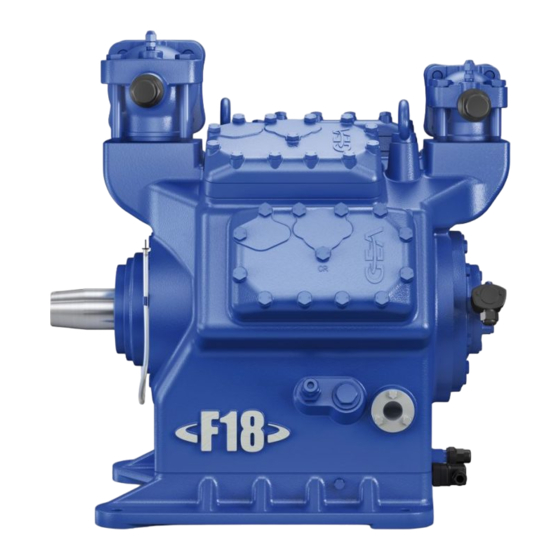
2 | Product description 2.1 Short description 8-cylinder open type compressor for external drive (V-belt or coupling) with oil pump lubrication Discharge shut-off valve Transport eyelet Suction shut-off valve Valve plate Cylinder cover Leak oil drain hose Shaft end Shaft seal Base plate Fig. -
Page 7: Type Code
2 | Product description 2.2 Name plate (example) GEA Bock GmbH 72636 Frickenhausen, Germany FX88/3235 BC12756A001 97,0 349,3 19/28 SE55 Fig. 3 Type designation Machine number Rotation speed minimum with a corresponding displacement Rotation speed maximum with a corresponding displacement ND(LP): Max. -
Page 8: Areas Of Application
3 | Areas of application 3.1 Refrigerants • HFKW / HFC: R134a, R404A/R507, R407C • (H)FCKW / (H)CFC: 3.2 Oil charge The compressors are filled with the following oil type at the factory: - for R134a, R404A/R507, R407C FUCHS Reniso Triton SE 55 - for R22 FUCHS Reniso SP 46 Compressors with ester oil charge (FUCHS Reniso Triton SE 55) are marked with an X in the type... - Page 9 3 | Areas of application 3.3 Operating limits R134a Unlimited application range Reduced suction gas Fig. 5 temperature Evaporating temperature (°C) Condensing temperature (°C) R404A/R507 Suction gas superheat (K) Suction gas temperature (°C) Permissible rotation speeds: 500 - 1800 rpm Fig.
-
Page 10: Compressor Assembly
4 | Compressor assembly INFO New compressors are factory-filled with inert gas. Leave this ser- vice charge in the compressor for as long as possible and prevent the ingress of air. Check the compressor for transport damage before starting any work. 4.1 Storage and transport Storage at (-30 °C) - (+70 °C), maximum permissible relative humidity 10 % - 95 %, no condensation... -
Page 11: Setting Up
4 | Compressor assembly 4.2 Setting up ATTENTION Attachments (e.g. pipe holders, additional units, fastening parts, etc.) directly to the compressor are not permissible! Provide adequate clearance for maintenance work. Provide adequate ventilation for the drive motor. Fig. 12 Do not use in a corrosive, dusty, damp atmosphere or a combustible environment. -
Page 12: Pipe Connections
4 | Compressor assembly 4.4 Pipe connections ATTENTION Risk of damages. Overheating can damage the valve. Remove the pipe supports from the valve for soldering. Only solder using inert gas to inhibit oxidation products (scale). The pipe connections have stepped internal diameters so that pipes with standard millimetre and inch dimensions can be used. - Page 13 4 | Compressor assembly Solenoid valve dead Non-return valve open Fig. 18 Important: Start unloader may only be employed during the starting phase. Check the solenoid valve and the non-return valve regularly for tightness. In addition, we recommend to use a heat protection thermostat on the discharge side of the com- pressor.
-
Page 14: Operating The Shut-Off Valves Gb
4 | Compressor assembly 4.8 Operating the shut-off valves Before opening or closing the shut-off valve, release the valve spindle seal by approx. 1 / 4 of a turn counter-clockwise. After activating the shut-off valve, re-tighten the adjustable valve spindle seal clockwise. Valve spindle seal loosen tighten... -
Page 15: Drive
- Maximum permissible axle load due to belt tension force: 9500 N. Direct drive with shaft coupling: Fig. 25 (schematical) Direct drive with shaft couplings demands highly precise aligning of compressor shaft and motor shaft. GEA Bock recommends the direct drive with centring a coupling housing (accessory). -
Page 16: Preparations For Start-Up
5 | Commissioning 5.1 Preparations for start-up INFO To protect the compressor against inadmissible operating conditions, high pressure and low pressure pressostats are mandatory on the installation side. The compressor has undergone trials in the factory and all functions have been tested. There are therefore no special running-in instructions. -
Page 17: Refrigerant Charge
5 | Commissioning 5.5 Refrigerant charge CAUTION Risk of injury! Contact with refrigerant can cause severe burns and skin damage. Avoid contact with refrigerant and wear personal protective clothing such as goggles and protective gloves! Make sure that the suction and discharge line valves are open. With the compressor switched off, add the liquid refrigerant directly to the condenser or receiver, breaking the vacuum. -
Page 18: Start-Up
5 | Commissioning 5.7 Start-up WARNING Ensure that both shut-off valves are open before starting the compressor! Check that the safety and protection devices (pressure switch, motor protection, electrical contact protection measures, etc.) are all functioning properly. Switch on the compressor and allow to run for a minimum of 10 min. Check the oil level by: The oil must be visible in the sight glass. -
Page 19: Maintenance
02279 Oil SE 55, 1 litre 02282 Only use genuine GEA Bock spare parts! 6.4 Shaft seal change As changing the shaft seal involves opening the refrigerant circuit, this is recommended only if the seal is losing refrigerant. Replacing the shaft seal is described in the spare part kit concerned. -
Page 20: Excerpt From The Lubricant Table
The oil grade filled as standard in the factory is noted on the name plate. This oil grade should be used preferably. Alternatives to this are listed in the following excerpt from our lubricant table. Refrigerant GEA Bock series oil grades Recommended alternatives FUCHS Reniso Triton SEZ 32... -
Page 21: Capacity Regulator
7 | Accessories 7.2 Capacity regulator ATTENTION If the capacity regulator is mounted at the factory, the control component (pilot valve) is mounted and connected subsequently by the customer. CR 2 CR 3 Delivery status 1 (ex works): Fig. 27 Cylinder cover prepared for capacity regulator. -
Page 22: Elevated Base Plate
Information about the use, operation, maintenance and servicing of the components is available in the printed literature or on the internet under www.gea.com. 7.3 Elevated base plate The compressor can be equipped with a elevated base plate. -
Page 23: Technical Data
8 | Technical data Shaft coupling Flywheel (belt pulley) Oil sump heater Rotation speed range Oil charge (sight glass centre) Oil charge ex works (sight glass top edge) Suction line Discharge line Weight Displacement (1450 / 1740 rpm) No. of cylinders Type... -
Page 24: Dimensions And Connections
Offenders will be held liable for the Indication of surface texture ment of damages. All rights reserved in the event payment of damages. All rights reserved in the event GEA Bock GmbH - Benzs GEA Bock Zust. / Rev. Zust. / Rev. - Page 25 9 | Dimensions and connections Suction line see technical data, Chapter 8 Discharge line Connection suction side, not lockable 8 “ NPTF Connection suction side, lockable 16 “ UNF Connection discharge side, not lockable 8 “ NPTF Connection discharge side, lockable 16 “...
-
Page 26: Declaration Of Incorporation
10| Declaration of incorporation Declaration of incorporation for incomplete machinery in accordance with EC Machinery Directive 2006/42/EC, Annex II 1. B Manufacturer: GEA Bock GmbH Benzstraße 7 72636 Frickenhausen, Germany We, as manufacturer, declare in sole responsibility that the incomplete machinery... -
Page 27: Service
The GEA Bock service team can be contacted by phone with a toll-free hotline 00 800 / 800 000 88 or via gea.com/contact. - Page 28 • • GEA Group is a global engineering company with multi-billion euro sales and operations in more than 50 countries. Founded in 1881, the company is one of the largest providers of innovative equipment and process technology. GEA Group is listed in the STOXX ®...
Need help?
Do you have a question about the Bock F88 and is the answer not in the manual?
Questions and answers