Table of Contents
Advertisement
Quick Links
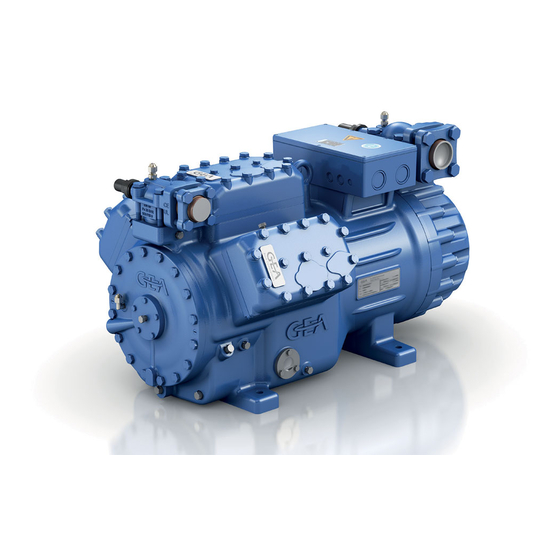
GEA Bock HG66e
Assembly instructions
96446-04.2019-Gb
Translation of the original instructions
HG66e/1340-4
HG66e/1540-4
HG66e/1750-4
HG66e/2070-4
HGX66e/1340-4
HGX66e/1540-4
HGX66e/1750-4
HGX66e/2070-4
HG66e/1340-4 S
HG66e/1540-4 S
HG66e/1750-4 S
HG66e/2070-4 S
HGX66e/1340-4 S
HGX66e/1540-4 S
HGX66e/1750-4 S
HGX66e/2070-4 S
Advertisement
Table of Contents

Related Manuals for GEA GEA Bock HG66e Series


Summary of Contents for GEA GEA Bock HG66e Series
- Page 1 GEA Bock HG66e Assembly instructions 96446-04.2019-Gb Translation of the original instructions HG66e/1340-4 HG66e/1340-4 S HG66e/1540-4 HG66e/1540-4 S HG66e/1750-4 HG66e/1750-4 S HG66e/2070-4 HG66e/2070-4 S HGX66e/1340-4 HGX66e/1340-4 S HGX66e/1540-4 HGX66e/1540-4 S HGX66e/1750-4 HGX66e/1750-4 S HGX66e/2070-4 HGX66e/2070-4 S...
- Page 2 Observe the safety instructions contained in these instructions. These instructions must be passed onto the end customer along with the unit in which the compres- sor is installed. Manufacturer GEA Bock GmbH 72636 Frickenhausen Contact GEA Bock GmbH Benzstraße 7...
-
Page 3: Table Of Contents
Contents Page Safety 1.1 Identification of safety instructions 1.2 Qualifications required of personnel 1.3 General safety instructions 1.4 Intended use Product description 2.1 Short description 2.2 Name plate 2.3 Type key Areas of application 3.1 Refrigerants 3.2 Oil charge 3.3 Limits of application Compressor assembly 4.1 Storage and transport 4.2 Setting up 4.3 Pipe connections 4.4 Pipes... -
Page 4: Safety
1| Safety 1.1 Identification of safety instructions: DANGER Indicates a dangerous situation which, if not avoided, will cause immediate fatal or serious injury. WARNING Indicates a dangerous situation which, if not avoided, may cause fatal or serious injury. CAUTION Indicates a dangerous situation which, if not avoided, may cause fairly severe or minor injury. -
Page 5: General Safety Instructions
The compressor may not be used in potentially explosive environments! These assembly instructions describe the standard version of the compressor named in the title man- ufactured by GEA. GEA refrigerating compressors are intended for installation in a machine (within the EU according to the EU Directives 2006/42/EC Machinery Directive, 2014/68/EU Pressure Equipment Directive). -
Page 6: Product Description
2 | Product description 2.1 Short description • Semi-hermetic six-cylinder reciprocating compressor with suction-gas cooled drive motor. • The stream of refrigerant sucked out of the evaporator flows over the motor and cools it intensively. In this way, the motor can be kept at a relatively low temperature level, particularly under high loads. -
Page 7: Type Key
2 | Product description 2.2 Name plate (example) GEA Bock GmbH 72636 Frickenhausen, Germany 380-420 Y/YY HGX66e/2070-4 180,0 BB12345-A001 440-480 Y/YY 107,0 A Y: 196,0 A YY: 335,0 A 217,2 IP 65 SE 55 Fig. 2 Type designation Voltage, circuit, frequency 50 Hz... -
Page 8: Areas Of Application
3 | Areas of application 3.1 Refrigerants • HFKW / HFC: R134a, R404A/R507, R407C, R407F • (H)FCKW / (H)CFC: R22 3.2 Oil charge The compressors are filled at the factory with the following oil type: - für R134a, R404A/R507, R407C, R407F FUCHS Reniso Triton SE 55 - für R22 FUCHS Reniso SP 46 Compressors with ester oil charge (FUCHS Reniso Triton SE 55) are marked with an X in the type designation (e.g. - Page 9 t = 20 °C t = 20 °C R513A 3 | Areas of application t (°C) 12,5 t (°C) t (°C) Maximum admissible Maximum admissible operating frequency: 60 Hz pressure (LP/HP) : 19/28 bar R513A LP = Low pressure HP = High pressure t (°C) t (°C) Unlimited application range...
- Page 10 t (°C) t (°C) 12,5 3 | Areas of application R513A Maximum admissible Maximum admissible operating frequency: 60 Hz pressure (LP/HP) : 19/28 bar t = 20 °C t (°C) LP = Low pressure HP = High pressure t (°C) 12,5 t = 20 °C Unlimited application range t (°C) t (°C)
-
Page 11: Compressor Assembly
4 | Compressor assembly INFO New compressors are factory-filled with inert gas. Leave this service charge in the compressor for as long as possible and pre- vent the ingress of air. Check the compressor for transport damage before starting any work. 4.1 Storage and transport Storage at (-30°C) - (+70°C), maximum permissible relative humidity 10% - 95%, no condensation... -
Page 12: Pipe Connections
4 | Compressor assembly 4.3 Pipe connections ATTENTION Damage possible. Superheating can damage the valve. Remove the pipe supports from the valve for soldering. Only solder using inert gas to inhibit oxidation products (scale). The discharge gas connection can be moved upwards with an adapter (accessory). -
Page 13: Laying Suction And Pressure Lines
4 | Compressor assembly Solenoid valve dead Non-return valve open Fig. 18 Important: Start unloader may only be employed during the starting phase. Check the solenoid valve and the non-return valve regularly for tightness. In addition, we recommend to use a heat protection thermostat on the discharge side of the com- pressor. -
Page 14: Operating The Shut-Off Valves
4 | Compressor assembly 4.7 Operating the shut-off valves Before opening or closing the shut-off valve, release the valve spindle seal by approx. 1 / 4 of a turn counter-clockwise. After activating the shut-off valve, re-tighten the adjustable valve spindle seal clockwise. Release Tighten Valve spindle seal... -
Page 15: Suction Pipe Filter
4 | Compressor assembly 4.9 Suction pipe filter For systems with long pipes and higher degree of contamination, a filter on the suction-side is recommended. The filter has to be be renewed depending on the degree of contamination (reduced pressure loss). 5| Electrical connection Electrical connection DANGER Risk of electric shock! High voltage! Only carry out work when the electrical system is disconnected from the power supply! ATTENTION When attaching accessories with an electrical cable, a minimum bending radius of 3 x the cable diameter must be maintained for... -
Page 16: Standard Motor, Design For Direct Or Partial Winding Start
5| Electrical connection 5.2 Standard motor, design for direct or partial winding start Designation on the name plate Sticker on the terminal box Y/YY Y/YY Compressors with this marking are suitable for direct or partial winding start. The motor winding is subdivided into two parts: Part winding 1 = 50 % and part winding 2 = 50 %. - Page 17 5 | Electrical connection The motor is wired for direct start (YY) at the factory. For part winding start Y/YY the bridges must be removed and the motor feed line connected according to the circuit diagram: 400 V Direktstart YY Teilwicklungsstart Y/YY Direct start YY Part winding start Y/YY...
- Page 18 5.3 Basic circuit diagram for part winding start with standard motor FC1.2 FC1.1 I> I> I> I> I> I> FC1.1 FC1.2 L3 N PE Y/YY B1 B2 INT69 Compressor terminal box Anschlußkasten Verdichter Fig. 24 High pressure safety monitor Safety chain (high/low pressure monitoring) Cold conductor (PTC sensor) motor winding Thermal protection thermostat (PTC sensor) Release switch (thermostat)
- Page 19 L1.1 L2.1 L3.1 L1.2 P> Θ Θ Θ DELTA- P II 6.c.8 FC1.1/1.2 Motor protection switch Control power circuit fuse INT69 G Electronic trigger unit INT69 G Delay relay for contactor switch over Main switch PW INT69 HG44/66 Mains contactor (part winding 1) Mains contactor (part winding 2) BOCK COMPRESSORS Control voltage switch...
-
Page 20: Special Motor: Design For Direct Or Star-Delta Start
5 | Electrical connection 5.4 Sondermotor: Ausführung für Direkt- oder Stern-Dreieck-Anlauf 5.4 Special motor: design for direct or star-delta start Für den Stern-Dreieck-Anlauf ist eine mechanische Anlaufentlastung mit Bypass-Magnetventil (Zubehör) erforderlich. A mechanical unloaded start with bypass solenoid valve is required for the star-delta start. Bezeichnung auf dem Typschild Aufkleber auf Klemmenkasten Designation on the name plate Sticker on the terminal box ∆... - Page 21 ∆ / Y ∆ / Y ∆ / Y 5 | Electrical connection Stern-Dreieck-Anlauf ist nur im Spannungsbereich ∆ (230 V) möglich. Beispiel: Stern-Dreieck-Anlauf ist nur im Spannungsbereich ∆ (230 V) möglich. Beispiel: Stern-Dreieck-Anlauf ist nur im Spannungsbereich ∆ (230 V) möglich. Beispiel: Star-delta start-up is only possible for ∆...
-
Page 22: Basic Circuit Diagram For Star-Delta Start 230 V ∆ / 400 V Y
5.5 Basic circuit diagram for star-delta start 230 V ∆ / 400 V Y FC1.1 I> I> I> FC1.1 FC1.2 FC1.2 I> I> I> L3 N PE ˜ B1 B2 INT69G Compressor terminal box Anschlußkasten Verdichter Fig. 25 High pressure safety monitor Safety chain (high/low pressure monitoring) Cold conductor (PTC sensor) motor winding Thermal protection thermostat (PTC sensor) - Page 23 L1.1 L2.1 L3.1 L1.2 P> Θ Θ Θ DELTA- P II 6.b.7 6.b.8 6.b.8 Control power circuit fuse INT69 G Electronic trigger unit INT69 G Delay relay for contactor switch over Main switch Mains contactor Δ-contactor D/S INT69 HG44/66 neu Y-contactor BOCK COMPRESSORS Control voltage switch...
-
Page 24: Electronic Trigger Unit Int69 G
5 | Electrical connection 5.6 Electronic trigger unit INT69 G The compressor motor is fitted with cold conductor temperature sensors (PTC) connected to the electronic trigger unit INT69 G in the terminal box. In case of excess temperature in the motor winding, the INT69 G deactivates the motor contactor. -
Page 25: Functional Test Of The Trigger Unit Int69 G
5 | Electrical connection 5.8 Function test of the trigger unit INT69 G Before commissioning, after troubleshooting or making changes to the control power circuit, check the functionality of the trigger unit. Perform this check using a continuity tester or gauge. Relay position INT69 G Gauge state Relay position... -
Page 26: Commissioning
6 | Commissioning 6.1 Preparations for start-up INFO To protect the compressor against inadmissible operating conditions, high pressure and low pressure pressostats are mandatory on the installation side. The compressor has undergone trials in the factory and all functions have been tested. There are therefore no special running-in instructions. -
Page 27: Refrigerant Charge
6| Commissioning 6.5 Refrigerant charge CAUTION Wear personal protective clothing such as goggles and protective gloves! Make sure that the suction and pressure line shut-off valves are open. With the compressor switched off, add the liquid refrigerant directly to the condenser or receiver, breaking the vacuum. If the refrigerant needs topping up after starting the compressor, it can be topped up in vapour form on the suction side, or, taking suitable precautions, also in liquid form at the inlet to the evaporator. -
Page 28: Maintenance
Item No. Item No. Item No. Item No. Set of gaskets kit 81652 81653 81654 81655 Valve plate kit 81633 81620 81621 81622 Oil pump kit 80950 Oil sump heater kit (220-240 V) 81252 Only use genuine GEA spare parts! -
Page 29: Extract From The Lubricants Table
7.4 Extract from the lubricants table The oil type filled as standard in the factory is marked on the name plate. This oil type should be used as a preference. Alternatives are stated in the extract from our lubricants table below. Refrigerants GEA standard oil types Recommended alternatives Fuchs Reniso Triton SEZ 32 HFKW... -
Page 30: Accessories
8| Accessories 8.1 Capacity regulator ATTENTION If the capacity regulator is installed at the factory, the control component (pilot valve) is subsequently installed and connected by the customer. LR 1 LR 2 Delivery condition 1 (from the factory): Fig. 30 Fig. 29 Cylinder cover prepared for capacity regulator. Cover Fig. -
Page 31: Oil Separator
Information about the use, operation, maintenance and servicing of the components is available in the printed literature or on the internet under www.gea.com. 8.2 Oil separator ATTENTION Oil slugging can result in damage to the compressor. -
Page 32: Oil Level Regulator
8| Accessories 8.3 Oil level regulator Oil level regulation systems have proven themselves with parallel circuits of several compressors. The connection "0" is provided for installing an oil level regulator (see dimensions drawing). All common mechanical oil level regulators from AC&R, ESK, Carly as well as the electronic oil level regulation system from AC&R, Teklab, OM3 TraxOil from Alco and ESK (only long version) can be connected directly without adapters (see fig.34). -
Page 33: Technical Data
9| Technical data Oil charge (sight glass centre) Oil charge (ex works) Suction line Discharge line Weight Starting current (rotor locked) Max. power consumption Max. operating current 380-420 V Y/YY - 3 - 50 Hz PW 440-480 V Y/YY - 3 - 60 Hz PW Voltage PW = Part Winding Winding ratio : 50 % / 50 %... -
Page 34: Dimensions And Connections
10| Dimensions and connections Centre of gravity H,D1 Anschlüsse / Connections Saugabsperrventil Suction line valve, Druckabsperrventi Discharge line valv Anschluss Saugse Connection suction Anschluss Saugse Connection suction Anschluss Druckse Connection discha Anschluss Druckse Connection discha HG66e/ Anschluss Öldruck Anschlüsse / HG66e/ 1340-4 (S) Connection oil pre... - Page 35 10| Dimensions and connections Suction line see technical data, chapter 9 Discharge line Connection suction side, not lockable “ NPTF 7 / 16 Connection suction side, lockable “ UNF 1 / 8 Connection discharge side, not lockable “ NPTF 7 / 16 Connection discharge side, lockable “...
-
Page 36: Declaration Of Incorporation
11| Declaration of incorporation Declaration of incorporation for incomplete machinery in accordance with EC Machinery Directive 2006/42/EC, Annex II 1. B Manufacturer: GEA Bock GmbH Benzstraße 7 72636 Frickenhausen, Germany We, as manufacturer, declare in sole responsibility that the incomplete machinery... -
Page 37: Service
12| Service Dear customer, GEA compressors are top-quality, reliable and service-friendly quality products. If you have any questions about installation, operation and accessories, please contact our technical service or specialist wholesaler and/or our representative. The GEA service team can be contacted by phone with a toll-free hotline 00 800 / 800 000 88 or via e-mail: info@gea.com Yours faithfully GEA Bock GmbH Benzstraße 7... - Page 38 • • GEA Group is a global engineering company with multi-billion euro sales and operations in more than 50 countries. Founded in 1881, the company is one of the largest providers of innovative equipment and process technology. GEA Group is listed in the STOXX ®...
Need help?
Do you have a question about the GEA Bock HG66e Series and is the answer not in the manual?
Questions and answers