Table of Contents
Advertisement
Quick Links
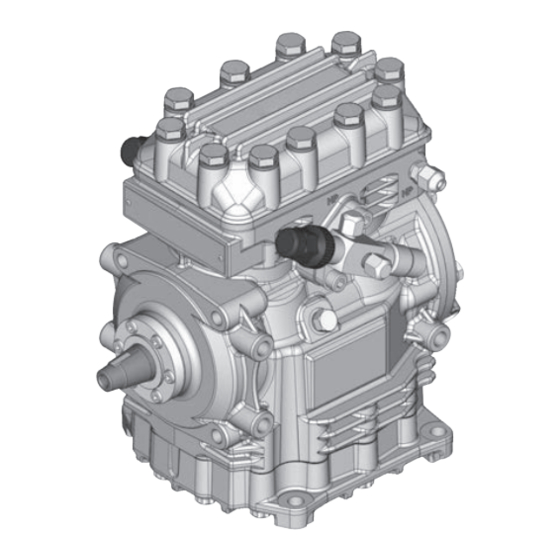
GEA Compressor FK20
Assembly instructions
09740-06.2016-Gb
Translation of the original instructions
FK20/120 N
FK20/145 N
FK20/120 K
FK20/145 K
FK20/120 TK
FK20/145 TK
FKX20/120 N
FKX20/145 N
FKX20/120 K
FKX20/145 K
FKX20/120 TK
FKX20/145 TK
FK20/170 N
FK20/170 K
FK20/170 TK
FKX20/170 N
FKX20/170 K
FKX20/170 TK
Advertisement
Table of Contents

Related Manuals for GEA FK20


Summary of Contents for GEA FK20
- Page 1 GEA Compressor FK20 Assembly instructions 09740-06.2016-Gb Translation of the original instructions FK20/120 N FK20/145 N FK20/170 N FK20/120 K FK20/145 K FK20/170 K FK20/120 TK FK20/145 TK FK20/170 TK FKX20/120 N FKX20/145 N FKX20/170 N FKX20/120 K FKX20/145 K FKX20/170 K...
- Page 2 Observe the safety instructions contained in these instructions. These instructions must be passed onto the end customer along with the unit in which the compressor is installed. Manufacturer GEA Bock GmbH 72636 Frickenhausen Contact GEA Bock GmbH Benzstrasse 7...
-
Page 3: Table Of Contents
Contents Page Safety 1.1 Identification of safety instructions 1.2 Qualifications required of personnel 1.3 General safety instructions 1.4 Intended use Product description 2.1 Brief description 2.2 Name plate 2.3 Type key Areas of application 3.1 Refrigerants 3.2 Oil charge 3.3 Limits of application 3.4 N and K versions 3.4.1 Limits of application R134a 3.4.2 Limits of application R407C 3.5 TK version... -
Page 4: Safety
1| Safety 1.1 Identification of safety instructions: Indicates a dangerous situation which, if not avoided, will cause DANGER! immediate fatal or serious injury. Indicates a dangerous situation which, if not avoided, may cause fatal or serious injury. WARNING! Indicates a dangerous situation which, if not avoided, may cause fairly severe or minor injury. -
Page 5: General Safety Instructions
0 °C on the suction side can be reached. 1.4 Intended use These assembly instructions describe the standard version of the FK20 manufactured by GEA. The compressor is intended for use in refrigeration systems in compliance with the limits of application. -
Page 6: Product Description
2| Product description 2.1 Brief description Three different designs are available for various ranges of application: > for air-conditioning the K Design > for air-conditioning or normal cooling the N Design > for deep freezing the TK Design The differences lie mainly in the valve plate tooling which is adapted to each applica- tion range where operational safety and efficiency are concerned. -
Page 7: Type Key
2| Product description 2.2 Name plate (example) AS12345A020 GEA Bock GmbH 72636 Frickenhausen, Germany FKX20/170N 14,8 19/28bar Fig. 3 Machine number Type designation Factory-filled oil type Displacement at 1450 rpm LP: Max. permissible operating pressure Observe the limits of application (g) Low pressure side diagrams! HP: Max. permissible operating pressure (g) High pressure side 2.3 Type key (example) -
Page 8: Areas Of Application
3| Areas of application 3.1 Refrigerants • HFKW / HFC: R134a, R404A/R507, R407C • (H)FCKW / (H)CFC: 3.2 Oil charge The compressors are factory-filled with the following oil type: - for R134a, R404A/R507, R407C FUCHS Reniso Triton SE 55 - for R22 FUCHS Reniso SP 46 Compressors w ith e ster o il c harge ( FUCHS R eniso T riton S E 5 5) a re m arked w ith a n X i n t he t ype d esignation (e.g. -
Page 9: N And K Versions
3| Areas of application 3.4 N and K versions Models available: • FKX20/120 N • FKX20/145 N • FKX20/170 N • FKX20/120 K • FKX20/145 K • FKX20/170 K 3.4.1 Limits of application R134a (N and K versions) Permissible rotation speeds: Max. permissible N Design: 500 – 3000 ¹/ (max rotation speed 3500 rpm) operating pressure (g) high- K Design: 500 –... -
Page 10: Tk Version
3| Areas of application 3.5 TK version R404A/R507 Models available: • FK20/120 TK • FK20/145 TK • FK20/170 TK • FKX20/120 TK • FKX20/145 TK • FKX20/170 TK 3.5.1 Limits of application R404A/R507 (TK version) R404A/R507 TK Permissible rotation speeds: Max. permissible operating pressure (g) high- TK design: 500 – 2600 ¹/ pressure side (HP): 28 bar t (°C) -
Page 11: Compressor Assembly
Check the compressor for transport damage before starting any work. 4.1 Setting up Fittings (e.g. pipe holders, additional units etc.) on the compressor are permissible only following consultation with GEA. Setup on an even surface or frame with sufficient load-bearing capacity. The compressor can be fastened as follows: - using the 4 drill holes on the baseplate - using the 3 side M10 tapped blind holes on the left or right of the compressor housing - using the 4 M10 tapped blind holes on the front of the compressor housing. -
Page 12: V-Belt Drive D
4| Compressor assembly 4.3 V-belt drive ATTENTION! Inappropriately designed belt drives, especially belt knocking or excessive tensioning forces can cause compressor damage! Make sure that the drive belt is designed correctly, e.g. by using tensioners and selecting the belt profile and the belt length. 4.4 Main bearing load To prevent the belt drive overloading the compressor main bearing, 600 N max = 30kNmm... -
Page 13: Pipe Connections
4| Compressor assembly 4.6 Pipe connections The pipe connections have graduated inside diameters so that pipes in the common millimeter and inch dimensions can be used. The connection diameters of the shut-off valves are designed for maximum compressor output. The required pipe cross-section must be matched to the capacity. -
Page 14: Operating Mode Of The Lockable Service Connections Tr
4| Compressor assembly 4.9 Operating mode of the lockable service connections Pipe connection Opening the shut-off valve: a) Spindle 1: turn to the left (counter-clockwise) as far as it will go. —> Shut-off valve fully opened / service connection 2 closed Fig. 15 Pipe connection Opening the service connection (2): b) Spindle 1: Turn ½ - 1 rotation to the right. —> Service connection 2 opened / shut-off valve opened. Fig. -
Page 15: Commissioning
5| Commissioning 5.1 Preparations for start-up INFO! To protect the compressor against inadmissible operating conditions, high-pressure and low-pressure pressostats are mandatory on the installation side. The compressor has undergone trials in the factory and all functions have been tested. There are therefore no special running-in instructions. -
Page 16: Refrigerant Charge
5| Commissioning 5.5 Refrigerant charge CAUTION! Wear personal protective clothing such as goggles and protective gloves! ATTENTION! Avoid overfilling the system with refrigerant! To avoid shifts in concentration, zeotropic refrigerant blends (e.g. R407C) must always be added to the refrigerating plant in liquid form. Do not pour liquid refrigerant through the suction line valve on the compressor. It is not permissible to mix additives with the oil and refrigerant. -
Page 17: Avoiding Liquid Shocks
5| Commissioning 5.7 Avoiding liquid shocks ATTENTION! Slugging can damage the compressor and cause refrigerant to leak. To prevent liquid shocks: The complete refrigeration plant must be correctly designed and executed. The capacities of all components must be compatible (particularly evaporator and expansion valve). Suction gas superheating at the evaporator output should be at least 7 – 10 K (check setting of the expansion valve). -
Page 18: Maintenance
Ref. No. Ref. No. Set of gaskets 80200 80515 Valve plate kit 80240 80242 80201 80202 80514 Set of shaft seals 08002 Oil SP 46, 1 litre 02279 Oil SE 55, 1 litre 02282 Only use genuine GEA spare parts! -
Page 19: Extract From The Lubricants Table
The oil type charged as standard in the factory is marked on the name plate. This oil type should be used as a preference. Alternatives are stated in the extract from our lubricants table below. Refrigerants GEA standard oil types Recommended alternatives Fuchs Reniso Triton SE 55 Fuchs SEZ 32/68/80 (e.g. -
Page 20: Accessories
7| Accessories 7.1 Thermal protection thermostat (Item No. 07595) A special intermediate flange, located below the discharge line valve, is used to attach the sensor element (Part no. 04175). Wire the thermal protection thermostat in series with the control line. Technical Data: Switching voltage max. : 24 V DC Switching current max. : 2.5 A at 24 V DC Switch-off temperature : 145 °C ± 5 K Switch-on temperature : approx. 115 °C... -
Page 21: Technical Data
8| Technical data No. of cylinders... -
Page 22: Dimensions And Connections
9| Dimensions and connections ca.215 ca.263 78,5 78,5 3xM10 beidseitig ca.150 both sides = Centre of gravity Dimensions in () = K Design Dimensions in mm Fig. 18 Shaft end 6x M5 View X A4x6,5 DIN 6888 3xM10 M8x22 beidseitig 24,7 34,3 36,3 55,1 Fig. 19 Dimensions in mm... - Page 23 9| Dimensions and connections Suction line see technical data, Chapter 8 Discharge line Connection suction side, not lockable 16 " UNF Connection suction side, lockable 16 " UNF Connection suction side, not lockable 8 " NPTF Connection discharge side, not lockable 16 "...
-
Page 24: Installation Certificate
(in accordance with Machinery Directive 2006/42/EC) The manufacturer: GEA Bock GmbH, Benzstraße 7 D-72636 Frickenhausen, Tel.: 07022/9454-0 hereby declares that the refrigerating compressor FK20 conforms to the essential requirements of Annex II 1B of the Machinery Directive 2006/42/EC. Applied harmonised standard: EN 12693:2008 and the corresponding standards referenced A partly completed machine may only be put into operation when it has been established that the machine, into which the partly completed machine is to be installed, conforms to the regulations of the Machinery Directive (2006/42/EC). -
Page 25: Service
11| Service Dear customer, GEA compressors are top-quality, reliable and service-friendly quality products. If you have any questions about installation, operation and accessories, please contact our technical service or specialist wholesaler and/or our representative. The GEA service team can be contacted by phone with a toll-free hotline 00 800 / 800 000 88 or via e-mail: info@gea.com Yours faithfully GEA Bock GmbH Benzstraße 7... - Page 26 • • GEA Group is a global engineering company with multi-billion euro sales and operations in more than 50 countries. Founded in 1881, the company is one of the largest providers of innovative equipment and process technology. GEA Group is listed in the STOXX ®...
Need help?
Do you have a question about the FK20 and is the answer not in the manual?
Questions and answers