Table of Contents
Advertisement
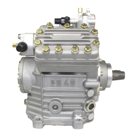
GEA Compressor FK40
Assembly instructions
09716-06.2016-Gb
Translation of the original instructions
FK40/390 N
FK40/390 K
FK40/470 N
FK40/470 K
FK40/560 N
FK40/560 K
FK40/655 N
FK40/655 K
FK40/755 K
FKX40/390 N FKX40/390 K FKX40/390 TK
FKX40/470 N FKX40/470 K FKX40/470 TK
FKX40/560 N FKX40/560 K FKX40/560 TK
FKX40/655 N FKX40/655 K FKX40/655 TK
FKX40/755 K
FK40/390 TK
FK40/470 TK
FK40/560 TK
FK40/655 TK
Advertisement
Table of Contents


Need help?
Do you have a question about the FK40 Series and is the answer not in the manual?
Questions and answers