
Related Manuals for GEA Grasso M-Series


Summary of Contents for GEA Grasso M-Series
- Page 1 Screw Compressor Packages GEA Grasso M-Series Operating Manual (Translation of the original text) P_261511_1...
-
Page 2: Step
These operating instructions have been written in good faith. However, GEA Refrigeration Germany GmbH cannot be held responsible for any errors that GEA Refrigeration Germany GmbH | P_261511_1 | Generated 01.04.2015... -
Page 3: Step
Hint! Stands for an important tip whose attention is important for the designa- ted use and function of the device. GEA Refrigeration Germany GmbH | P_261511_1 | Generated 01.04.2015... - Page 4 2. Handling sequence step 2 The subsequent handling sequence is the expected result: ® Result of the handling sequence. Individual handling steps Individual handling steps are marked thus: – Individual work steps GEA Refrigeration Germany GmbH | P_261511_1 | Generated 01.04.2015...
-
Page 5: Table Of Contents
7.7.4 Oil separator 7.7.5 OMC block with oil filter system 7.7.6 Oil cooler 7.7.7 Oil pump (optional) 7.7.8 Suction filter - check valve combination 7.7.9 Controller 7.7.10 Fittings 7.7.11 Safety devices GEA Refrigeration Germany GmbH | P_261511_1 | Generated 01.04.2015... - Page 6 Setting of setpoint and limiting values as well as safety devices Operation of the screw compressor package Instructions regarding failures, their causes and remedies 10 CLEANING, MAINTENANCE, REPAIR 10.1 Use in explosive atmospheres, installation zones 1 and 2 GEA Refrigeration Germany GmbH | P_261511_1 | Generated 01.04.2015...
- Page 7 11.2 Standstill for a period <48 hours 11.3 Standstill for a period >48 hours 11.4 Measures during shutdowns 11.4.1 Monthly measures during standstill 11.4.2 Four weeks before restarting 12 DECOMMISSIONING, DISPOSAL GEA Refrigeration Germany GmbH | P_261511_1 | Generated 01.04.2015...
- Page 8 Operating Manual | GEA Grasso M-Series Screw Compressor Packages GEA Refrigeration Germany GmbH | P_261511_1 | Generated 01.04.2015...
- Page 9 GEA Grasso M-Series, arrangement of the coupling housing fig. 22 GEA Grasso M-Series, arrangement of the oil separator fig. 23 GEA Grasso M-Series, arrangement of the OMC block with oil filter system fig. 24 GEA Grasso M-Series, arrangement of the oil cooler fig. 25 GEA Grasso M-Series, arrangement of the (optional) oil pump fig.
- Page 10 Operating Manual | GEA Grasso M-Series Screw Compressor Packages GEA Refrigeration Germany GmbH | P_261511_1 | Generated 01.04.2015...
-
Page 11: Basics
– Deficiencies noticed in the electrical systems/ tion in training measures, have sufficient knowledge modules/tools and fixtures must be corrected immediately. If an acute danger exists till then, GEA Refrigeration Germany GmbH | P_261511_1 | Generated 01.04.2015... -
Page 12: Legal Foundations (Germany)
The mandatory accident prevention regulations applicable for the respective country and area where the product is used must also be observed. GEA Refrigeration Germany GmbH | P_261511_1 | Generated 01.04.2015... - Page 13 Operating Manual | GEA Grasso M-Series Basics Screw Compressor Packages Failure to observe the safety instructions can lead to danger to personnel and the environment as well as damage to the unit. GEA Refrigeration Germany GmbH | P_261511_1 | Generated 01.04.2015...
-
Page 14: Specified Use
– mechanical components are wrongly connected. teed. The supplier/installer or the operator – and not GEA Refrigeration Germany GmbH | P_261511_1 | Generated 01.04.2015... -
Page 15: Ce Mark
Germany GmbH is provided as defined in the Pres- sure Equipment Directive, i.e. pressure equipment is placed on the market with the required equipment parts with safety function. This complete assembly is subject to the Pressure Equipment Directive. GEA Refrigeration Germany GmbH | P_261511_1 | Generated 01.04.2015... -
Page 16: Manufacturer Information
GEA Refrigeration Germany GmbH Factory Halle Berliner Straße 130 06258 Schkopau/ OT Döllnitz, Germany Tel.: +49 345 78 236 - 0 Fax: +49 345 78 236 - 14 Web: www.gea.com E-Mail: refrigeration@gea.com GEA Refrigeration Germany GmbH | P_261511_1 | Generated 01.04.2015... -
Page 17: Customer Service
GEA Refrigeration Germany GmbH has its own prac- tical and rapidly working spare parts department to supply the necessary spare parts worldwide. Neces- sary spare parts are shipped as quickly as possible. GEA Refrigeration Germany GmbH | P_261511_1 | Generated 01.04.2015... -
Page 18: Safety
– fracture during operation, ted and provided with an emergency stop switch. – operating media or objects getting thrown out, – loss of stability and – personnel slipping, tripping or falling. GEA Refrigeration Germany GmbH | P_261511_1 | Generated 01.04.2015... -
Page 19: Installation In Explosive Atmospheres, Installation Zones 1 And
The maintenance may only be carried out in agreement/with the knowledge and release of If oil heaters are used in potentially explosive the owner operator. atmospheres (see component specification), additional, separate oil level monitoring is abso- GEA Refrigeration Germany GmbH | P_261511_1 | Generated 01.04.2015... - Page 20 – Each maintenance inspection (see maintenance book) must also include checking the secure fit of the threaded connections for the coupling safety hood. GEA Refrigeration Germany GmbH | P_261511_1 | Generated 01.04.2015...
-
Page 21: Transport, Storage
It is forbidden to attach SCPs to fit- tings or pipes or at the eyebolts / lift- ing rings of the compressor, the elec- tric motor, the tank or the switching cabinet. GEA Refrigeration Germany GmbH | P_261511_1 | Generated 01.04.2015... -
Page 22: Fig. 3 Stopper With Shackle
Make suitable arrangements (timber or insulating material) to avoid damage to the surface. Shackles must be used. fig.3: Stopper with shackle fig.4: Transportation with a wire rope hoist GEA Refrigeration Germany GmbH | P_261511_1 | Generated 01.04.2015... -
Page 23: Bearings
Up until this point in time, the foil serves to protect the screw compres- sor package against external influences. GEA Refrigeration Germany GmbH | P_261511_1 | Generated 01.04.2015... -
Page 24: Storage (Several Years)
The following storage conditions must be maintained when storing screw compressor packages that are equipped with a control. 1. Storage temperature > 10°C GEA Refrigeration Germany GmbH | P_261511_1 | Generated 01.04.2015... - Page 25 Please pay attention to the information in the "Start-up" chapter. The general check includes changing the O-ring on the compressor shaft seal as well as replacing the shaft seal of the oil pump. GEA Refrigeration Germany GmbH | P_261511_1 | Generated 01.04.2015...
-
Page 26: Installation
The frame of the screw compressor unit/ liquid chiller is placed on foundation bolts on a prepared founda- tion. The frame must be levelled with suitable shims such that the coarse alignment (radial and angular GEA Refrigeration Germany GmbH | P_261511_1 | Generated 01.04.2015... -
Page 27: Use In Explosive Atmospheres, Installation Zones 1 Und
(2003/10/EC Article 6). Hint! The screw compressor package is not intended for unprotected outdoor installation. Protection against exter- nal influences, especially dirt, dust and moisture (wetness), is essential. GEA Refrigeration Germany GmbH | P_261511_1 | Generated 01.04.2015... - Page 28 Operating Manual | GEA Grasso M-Series Screw Compressor Packages Sound power level L in dB(A) Compressor type/theoretical throughput volume in m /h at 4500 RPM Compressor drive motor output in kW 1056 1316 GEA Refrigeration Germany GmbH | P_261511_1 | Generated 01.04.2015...
-
Page 29: Description Of Design And Function
To this end, a sepa- rate oil level switch is used in each use case according to the necessary explosion protec- tion specifications – see also the component specifications in the product description. GEA Refrigeration Germany GmbH | P_261511_1 | Generated 01.04.2015... -
Page 30: Product Code Of Screw Compressor Packages - Grasso Sp1, Sp2, Spduo And M Series
X / (X1) Screw compressor package size Code letter Theoretical volume flow Code letter Theoretical volume flow at 2940 min in m³/h at 2940 min in m³/h 1460 1740 1940 2390 2748 GEA Refrigeration Germany GmbH | P_261511_1 | Generated 01.04.2015... - Page 31 Vi = 3.6 Standard refrigerating compressor Vi = 4.8 Standard refrigerating compressor Vi = 5.5 Standard refrigerating compressor Vi = variable Booster Vi = fixed Heat pump compressor Vi = fixed or variable GEA Refrigeration Germany GmbH | P_261511_1 | Generated 01.04.2015...
-
Page 32: Technical Specifications
Technical specifications – general assembly drawing, – P+I diagram. Packages / chillers are designed and manufactured for special fields of application. For technical specifi- cations see the following. – order specification, GEA Refrigeration Germany GmbH | P_261511_1 | Generated 01.04.2015... -
Page 33: Location Of The Product Identification (Name Plate)
Germany GmbH turer Type: Type designation of the screw compressor package Serial no.: Serial number of the screw compressor package Year of construc- Year of construction of the tion: screw compressor package GEA Refrigeration Germany GmbH | P_261511_1 | Generated 01.04.2015... -
Page 34: Information And Safety Labels On The Product
HLP type series. Counter-hold the screwed pipe connection using a wrench. Tighten the pipe nut about rotation beyond the point where the increase in the force if felt. ® The leakage is remedied. GEA Refrigeration Germany GmbH | P_261511_1 | Generated 01.04.2015... -
Page 35: Labels Of The Pipelines
(information plate) fig.13: Marking the direction of rotation of the oil pump motor The direction of arrow indicates the direction of rota- tion of the oil pump motor GEA Refrigeration Germany GmbH | P_261511_1 | Generated 01.04.2015... -
Page 36: Labels Of The Pressure Gauge
The description of the pressure gauge measuring point is attached directly underneath the pressure gauge. The gauge board can be arranged horizon- tally as well as vertically. fig.15: Test verification for the control system GEA Refrigeration Germany GmbH | P_261511_1 | Generated 01.04.2015... -
Page 37: Designation Of The Earth Connection
Connect the earth connection. The neces- sary mounting hardware and cables are not included in scope of supply. Process flow diagram fig.17: Process flow diagram Grasso SP1, M-series Suction side Compressor Oil separator Pressure side GEA Refrigeration Germany GmbH | P_261511_1 | Generated 01.04.2015... -
Page 38: Main Components
Description of Design and Function Operating Manual | GEA Grasso M-Series Screw Compressor Packages Main components Screw compressor packages within the Grasso M-series series consist of the following main assemblies and components: Hint! The documentation of the main components is... -
Page 39: Screw Compressor
The screw compressors are driven directly by the compressor drive motor via a flexible coupling. Hint! The documentation of the screw com- pressor (installation instructions, part lists, drawings) is an integral product documentation. GEA Refrigeration Germany GmbH | P_261511_1 | Generated 01.04.2015... -
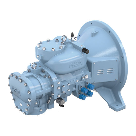
Page 40: Compressor With Coupling Housing
7.7.3 Compressor with coupling hous- 7.7.4 Oil separator fig.22: GEA Grasso M-Series, arrangement of the oil separator fig.21: GEA Grasso M-Series, arrangement of the coupling housing The design of the oil separators is standardised and features reduced oil carry-over and low oil consump- The coupling housing contains the coupling and is tion. -
Page 41: Omc Block With Oil Filter System
7.7.5 OMC block with oil filter system fig.24: GEA Grasso M-Series, arrangement of the oil cooler The oil cooler is used for cooling the oil heated in the compressor in order to ensure sufficient oil viscosity for supplying to the compressor. -
Page 42: Suction Filter - Check Valve Combination
It is used for pumping and distributing refrig- erating machine oil. fig.26: GEA Grasso M-Series, suction filter - check valve com- The oil pump ensures that the oil is distributed to the bination individual lubrication points (e.g. journal bearing, bal- ance piston and packing gland of the compressor). -
Page 43: Controller
Furthermore, all kinds of installations in piping, such as sight glasses, measurement apertures, filters and The GEA Omni consists of the control unit with oper- similar are also designated as fittings. Therefore, fit- ator keypad and display unit, indicator lights for tings also include all kinds of valves, such as: "Running", "Warning"... -
Page 44: Safety Devices
The valve is available as an option, depending on charge pressure falls below the specified limit value the required acceptance. after a delay period. Limit value = see parameter list GEA Refrigeration Germany GmbH | P_261511_1 | Generated 01.04.2015... -
Page 45: Monitoring Devices
– Used refrigerant the screw compressor. The pressure side check valve prevents refrigerant – Controled value from re-condensing in the oil separator. – Used options GEA Refrigeration Germany GmbH | P_261511_1 | Generated 01.04.2015... -
Page 46: Oil System
The oil heater on the oil separator is to be started when the package is shut down in order to ensure a minimum oil temperature and sufficient oil viscosity required for restarting the package. The oil heating is GEA Refrigeration Germany GmbH | P_261511_1 | Generated 01.04.2015... -
Page 47: Oil Injection
The control slide travel speeds in the MIN and MAX directions should, to the extent possible, be the same during operation to ensure better compressor control. 7.12 Technical specifications GEA Refrigeration Germany GmbH | P_261511_1 | Generated 01.04.2015... -
Page 48: Basic Terms
The tabulated data apply for single, two-stage and heat pump operation. Depend- ing on the compressor the manufacturer selected, the specific operating conditions limitations may occur within the parameters in the table. GEA Refrigeration Germany GmbH | P_261511_1 | Generated 01.04.2015... - Page 49 1. Compressors for a discharge pressure up to 52 Hint! bar (currently not available) are equipped with All of the following requirements must housings made of a material of higher strength be observed! and are fitted with special components. GEA Refrigeration Germany GmbH | P_261511_1 | Generated 01.04.2015...
-
Page 50: Water Quality Requirements, Parameters
0,1 K/s. 12. Rotation direction: view of compressor’s driving shaft clockwise. 13. For individual cases outside the permitted speed coordination needs to made with the manufac- turer. GEA Refrigeration Germany GmbH | P_261511_1 | Generated 01.04.2015... -
Page 51: Fig. 28 Corrosion Resistance In Presence Of Chlorides
Corrosion resistance in presence of chlorides Chloride ion concentration in ppm Cl Chloride < 150 g/m³ Wall temperature heat exchanger in °C Sulphur < 325 g/m³ AISI 304 AISI 316 SMO 254 GEA Refrigeration Germany GmbH | P_261511_1 | Generated 01.04.2015... - Page 52 The manufacturer recommends enlisting the services of a reputable water conditioning company. GEA Refrigeration Germany GmbH | P_261511_1 | Generated 01.04.2015...
-
Page 53: Start-Up
Factory setting of the safety and monitoring devi- must be read prior to commencing start-up work. Familiarise yourself with the evacuation plan of • Works trial runs (at the request of the client) the installation location. GEA Refrigeration Germany GmbH | P_261511_1 | Generated 01.04.2015... -
Page 54: Basics
Caution! All electrical connections must be made according to the circuit diagram which is valid for the project. The cir- cuit diagram is part of the product documentation. GEA Refrigeration Germany GmbH | P_261511_1 | Generated 01.04.2015... -
Page 55: Electrical Connection
A pressure drop of 2% is allowed during the 3 hours. connections must be made according to the circuit Fluctuations in the ambient temperature must be diagram, e.g. taken into account. – Compressor drive motor GEA Refrigeration Germany GmbH | P_261511_1 | Generated 01.04.2015... -
Page 56: Drying, Vacuum
3 hours. Evacuation is used to remove air and moisture from the plant. A vacuum pump must be used for evacuation. The permissible increase in vacuum is maximum 6.66 mbar over a period of 3 hours. GEA Refrigeration Germany GmbH | P_261511_1 | Generated 01.04.2015... -
Page 57: Operating Position Of Valves
Stop valve open Stop valve closed during normal operation fig.31: Stop valve closed Check valve during normal operation fig.32: Check valve Shuttable check valve open during normal operation fig.33: Shuttable check valve GEA Refrigeration Germany GmbH | P_261511_1 | Generated 01.04.2015... -
Page 58: Fig. 34 Control Valve
An oil pressure being set too high or too low may result in serious compressor damage or even the total breakdown of the compressor after just a short period of operation! GEA Refrigeration Germany GmbH | P_261511_1 | Generated 01.04.2015... -
Page 59: Fig. 39 Overflow Valve, Safety Valve
Quick acting valve, spring-loaded – ½” connections – with cap fig.42: Charging valve, drain valve – Connection Rp ¼” – For pressure gauge and pressure transmitter fig.43: Service valve GEA Refrigeration Germany GmbH | P_261511_1 | Generated 01.04.2015... -
Page 60: Oil Charge
990565) and lower edge of the sight glass indicator cally blocked (service). The stop valves are in the MAX (N10c, data sheet 990565). operating position. The oil separator is generally charged with oil via the oil cooler. GEA Refrigeration Germany GmbH | P_261511_1 | Generated 01.04.2015... -
Page 61: Checking The Fault Monitoring
3. Resetting of the emergency-OFF actuation to 6. "Oil circuit monitoring failure” must be indicated end the test. after a starting delay time of 20 sec. 7. Reconnect the oil pump motor to the mains sup- ply. GEA Refrigeration Germany GmbH | P_261511_1 | Generated 01.04.2015... -
Page 62: Adjustment Of Oil Pressure
Motor direction of rotation (075). Compressor For adjustment solely the oil pump must be started. For units with the control GEA Omni, digital output Motor must be forced for this. The set value of the oil differential pressure should –... -
Page 63: Checking The Water Circuits
3. The maximum end position (100%) must be No regulating or checking required. reached and signalled when the "Increase power" button is pressed. 8.5.17 Adjusting the amount of injection oil and the oil temperature GEA Refrigeration Germany GmbH | P_261511_1 | Generated 01.04.2015... -
Page 64: Screw Compressor Packages Without Refrigerant Injection
2. Switching on the control unit according to the operating manual. 3. Checking all parameters on the control unit dis- play. See parameter list. 4. Checking the settings of all control and safety devices. GEA Refrigeration Germany GmbH | P_261511_1 | Generated 01.04.2015... -
Page 65: Use, Operation, Control
2. The screw compressor package must be suffi- ciently filled with refrigerant and oil. 3. The valves must be in the operating position. 4. The oil level in the oil separator must be within the permissible range. GEA Refrigeration Germany GmbH | P_261511_1 | Generated 01.04.2015... - Page 66 8. The rated current limitation has been set accord- ing to the motor rating. ® The screw compressor package can be switched on as per the controller operating manual. GEA Refrigeration Germany GmbH | P_261511_1 | Generated 01.04.2015...
-
Page 67: Overview Of The Operating Modes
Start/stop and capacity demand via network from a Network Network remote master controller. The master also generates + Net (pulse) pulses the +/- signals as pulses for controlling the capacity directly. GEA Refrigeration Germany GmbH | P_261511_1 | Generated 01.04.2015... - Page 68 The GSC TP controls the output depending on + Bus (net. + setpoint Setpoint an external setpoint sent externally via the network deviation and from this setpoint also automatically switches the product ON/OFF. GEA Refrigeration Germany GmbH | P_261511_1 | Generated 01.04.2015...
-
Page 69: Setting Of Setpoint And Limiting Values As Well As Safety Devices
GEA Refrigeration Germany GmbH are highly advanced, automatic and extremely efficient The GEA Omni consists of the control unit with oper- systems. Nevertheless, faults can occur and may ator keypad and display unit (TouchPanel), indicator complicate any continuous operation of the plant or lights for "Running", "Warning"... - Page 70 The compressors are shut off very The suction pressure is too low. Open all valves on the suction side often by the minimum pressure of the compressors. governor. GEA Refrigeration Germany GmbH | P_261511_1 | Generated 01.04.2015...
- Page 71 When operting, the package/chiller The compressor(s) or the drive Inform the GEA Refrigeration Ger- is louder than permitted. motor(s) is/are defective. many GmbH customer service GEA Refrigeration Germany GmbH | P_261511_1 | Generated 01.04.2015...
-
Page 72: 10 Cleaning, Maintenance, Repair
10.2 Important information for service 10.3 Cleaning the heat exchanger personnel The following chapter is primarily aimed at the main- tenance and service personnel of the screw com- pressor package. GEA Refrigeration Germany GmbH | P_261511_1 | Generated 01.04.2015... -
Page 73: Mechanical Cleaning
Parts of the system under pressure must be com- pletely vented before opening. While carrying out the repair, it is must always be ensured that a complete pressure balance of the affected pressure chambers with the environment is preserved. GEA Refrigeration Germany GmbH | P_261511_1 | Generated 01.04.2015... -
Page 74: Repair Work
Measure axial play of bearings, – Check shaft seal, Hint! – Check primary slide movement, The responsible monitoring body (e.g.TÜV) must be notified in advance. – Check the adjustment of the position sensor. GEA Refrigeration Germany GmbH | P_261511_1 | Generated 01.04.2015... -
Page 75: Changing The Block Mounting Filter Element
50% of the value before 8. Carefully insert a new oil filter element. replacing the filter element, wire mesh must also 9. Close the cover of the oil filter. be replaced. GEA Refrigeration Germany GmbH | P_261511_1 | Generated 01.04.2015... -
Page 76: Maintenance Of The Suction Filter
7. Reassemble all parts with the new or cleaned fil- Oil change with freon as the refrig- ter element following the same procedure in erant after 10,000operating hours or reverse order. after 2 years at the latest. GEA Refrigeration Germany GmbH | P_261511_1 | Generated 01.04.2015... - Page 77 3. Open the stop valve in the bypass line around the check valve on the suction side and the stop valve on the suction side to equalise the pres- GEA Refrigeration Germany GmbH | P_261511_1 | Generated 01.04.2015...
-
Page 78: Oil Pump Maintenance
1/2 filling level of sight glass N10b (MIN - The fine oil separation cartridges should be replaced standstill), oil must be replenished. no later than after 25,000 run hours or 5 years. GEA Refrigeration Germany GmbH | P_261511_1 | Generated 01.04.2015... -
Page 79: Tightening Screw Fastenings
The site of GEA Refrigeration Germany GmbH | P_261511_1 | Generated 01.04.2015... -
Page 80: Venting The Refrigerant Circuit
The use of increases. A pressure comparison is based on a foaming agents gives the best results at test pres- constant ambient temperature. sures < 5 bar. GEA Refrigeration Germany GmbH | P_261511_1 | Generated 01.04.2015... -
Page 81: Checking The Bearing Noise
The project-related setting values and limits are given in the parameter list. Inform the manufacturer contract partner if the parameters are outside the allowable limits. GEA Refrigeration Germany GmbH | P_261511_1 | Generated 01.04.2015... -
Page 82: Maintenance Of The Switching Cabinet
10.4.4.21 Maintenance of the switching cabinet Terminal screws must be checked for tightness and, if necessary, tightened at regular intervals (every 5,000 operating hours or at least once per year). The GEA Refrigeration Germany GmbH | P_261511_1 | Generated 01.04.2015... -
Page 83: Checking The Earth Connection
DIN, unless otherwise specified. Hint! The tightening torques for the adjust- ing elements should be obtained from the data sheet. The data sheet forms part of the product documentation. GEA Refrigeration Germany GmbH | P_261511_1 | Generated 01.04.2015... -
Page 84: 11 Decommissioning
2. If necessary, shut down all ancillary drives. down for a period longer than half a year. The mois- GEA Refrigeration Germany GmbH | P_261511_1 | Generated 01.04.2015... -
Page 85: Monthly Measures During Standstill
– Check the insulation resistance of the drive motors (see the operating manual for the electric motor). – Switch on the oil pump. – Check the screw compressor package/chiller for leakages. GEA Refrigeration Germany GmbH | P_261511_1 | Generated 01.04.2015... -
Page 86: 12 Decommissioning, Disposal
Personal protective equipment compliant with EN 378-3 must be worn. – National regulations (e.g. EN 378-4, Section 6) must be observed for the reclamation and dis- posal of refrigerants. GEA Refrigeration Germany GmbH | P_261511_1 | Generated 01.04.2015... - Page 87 Operating Manual | GEA Grasso M-Series Decommissioning, disposal Screw Compressor Packages GEA Refrigeration Germany GmbH | P_261511_1 | Generated 01.04.2015...
Need help?
Do you have a question about the Grasso M-Series and is the answer not in the manual?
Questions and answers