
Related Manuals for Generac Power Systems MLT4150


Summary of Contents for Generac Power Systems MLT4150
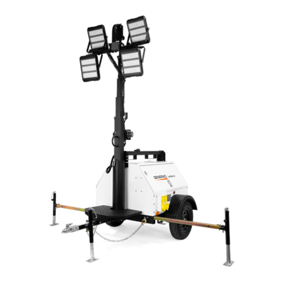
- Page 1 Owner’s Manual Light Tower MLT4150 SN 3004595385 and higher 004645 For technical assistance contact: www.generacmobile.com Technical Service 1-800-926-9768 SAVE THIS MANUAL FOR FUTURE REFERENCE...
- Page 2 Use this page to record important information about your light tower Record the information found on your unit data label on this page. See unit serial number location (Unit Serial Unit Model No. Number Locations). The label plate is affixed to the inside partition, to the left of the control panel console.
-
Page 3: Table Of Contents
Table of Contents Section 1: Introduction and Safety Emergency Stop Switch ..........15 Starting the Unit ............15 Introduction ..............1 Read This Manual Thoroughly ........1 Automatic Shutdown ..........16 How to Obtain Service..........1 Light Operation ............16 Safety Rules ..............1 Auxiliary Outlets ............17 General Hazards............2 Wet Stacking ...............17 Explosion and Fire Hazards .........2 Voltage Regulator ............17... - Page 4 AC Wiring—Receptacle Panel Options (If Equipped) (1 of 2)................32 AC Wiring—Receptacle Panel Options (If Equipped) (2 of 2)................33 DC Wiring ..............34 DC Wiring—Options (If Equipped) ......35 Trailer Lights............... 36 Owner’s Manual for Mobile Light Tower...
-
Page 5: Section 1: Introduction And Safety
Section 1: Introduction and Safety Introduction Safety Rules Thank you for purchasing a Generac Mobile product. This The manufacturer cannot anticipate every possible unit has been designed to provide high performance, circumstance that might involve a hazard. The warnings in efficient operation, and years of use when maintained this manual, and on tags and decals affixed to the unit are, properly. -
Page 6: General Hazards
Introduction and Safety General Hazards Explosion and Fire Hazards DANGER DANGER Asphyxiation. Running engines produce Explosion and Fire. Fuel and vapors are carbon monoxide, a colorless, odorless, extremely flammable and explosive. Add fuel poisonous gas. Carbon monoxide, if not in a well ventilated area. Keep fire and spark avoided, will result in death or serious injury. -
Page 7: Electrical Hazards
Introduction and Safety Electrical Hazards Battery Hazards DANGER DANGER Electrocution. In the event of electrical accident, Electrocution. Do not wear jewelry while immediately shut power OFF. Use non-conductive working on this equipment. Doing so will implements to free victim from live conductor. Apply result in death or serious injury. -
Page 8: Fuel Hazards
Introduction and Safety Fuel Hazards Operating Safety DANGER Positioning the Unit Explosion and fire. Fuel and vapors are extremely DANGER flammable and explosive. No leakage of fuel is permitted. Keep fire and spark away. Failure to do High Voltage. Verify area above unit is clear of overhead wires and obstructions. -
Page 9: Raising And Lowering The Mast
Introduction and Safety Service Safety Raising and Lowering the Mast WARNING This unit uses high voltage circuits capable of causing serious injury or death. Only a qualified and licensed Electrocution. Do not set up or operate electrician should troubleshoot or repair problems this unit if severe weather is expected. -
Page 10: Towing Safety
Introduction and Safety Towing Safety Reporting Trailer Safety Defects Towing a trailer requires care. Both the trailer and vehicle If you believe your trailer has a defect which could cause must be in good condition and securely fastened to each a crash or could cause injury or death, you should other to reduce the possibility of an accident. -
Page 11: Section 2: General Information
Section 2: General Information Specifications Description Unit of Measure MLT4150 Engine ® Make (Model) — Mitsubishi (S4L2) Cylinders Displacement 107.3 (1.76) Horsepower—Prime hp (kW) 22.4 (16.7) Horsepower—Standby hp (kW) 24.3 (18.1) Operating Speed 1,800 Fuel Consumption—100% load gph (Lph) 1.35 (5.1) -
Page 12: Unit Dimensions
General Information Unit Dimensions ###### Figure 2-1. Unit Dimensions 170 in (4.32 m) 70 in (1.78 m) 30 ft (9.14 m) 68 in (1.73 m) 140 in (3.56 m) Specifications are subject to change without notice. Owner’s Manual for Mobile Light Tower... -
Page 13: Unit Serial Number Locations
General Information Unit Serial Number Locations Refer to the illustration to locate the unit ID tag and on these tags. Record the information from these tags so Vehicle Identification Number (VIN) tag on the unit. it is available if the tags are lost or damaged. When Important information, such as the unit serial number, ordering parts or requesting assistance, you may be model number, VIN and tire loading information are found... -
Page 14: Component Locations
General Information Component Locations LEFT SIDE RIGHT SIDE Figure 2-3. Component Locations A Mast rotation knob G Emergency stop switch B Central lifting point H Radiator (inside unit) C Engine exhaust I Upper forklift pocket (2 locations) D Battery (inside unit) J Fuel fill (behind door) E Lower Forklift pocket (2 locations) K Outrigger (2 locations) -
Page 15: Control Panel
General Information Control Panel BALLAST INDICATOR LIGHTS MAIN BREAKER 240V TURN MAIN BREAKER LIGHT SWITCHES GLOW PLUG INDICATOR GLOW PLUG START BREAKER NEUTRAL BONDED TO FRAME 004625 Figure 2-4. Control Panel (A) Circuit Breaker Indicator Light (F) Glow Plug Indicator This light indicates that the main circuit breaker must be Indicates operation of the engine glow plugs. - Page 16 General Information This page intentionally left blank. Owner’s Manual for Mobile Light Tower...
-
Page 17: Section 3: Operation
Section 3: Operation Unit Set-Up DETAIL C DETAIL D DETAIL G DETAIL H 004659 Figure 3-1. Set-Up Components 3. Pull locking pin on tongue jack (B). Rotate the jack 90°. Reinstall locking pin. Rotate jack handle DANGER clockwise to raise trailer tongue off towing vehicle. High Voltage. -
Page 18: Prestart Checklist
Operation Raising the Mast 8. Before raising the mast, it may be necessary to adjust the lamps. The lamps may be adjusted up, 1. Set up and level the unit. See Unit Set-Up. down, left or right by loosening the wing nuts on the trunnion (H) and aiming the lamps in the desired DANGER direction. -
Page 19: Emergency Stop Switch
Operation 3. Check the mast cables for excessive wear or The switch will remain closed until it is pulled out. damage. Verify the cables are properly centered in NOTE: Use the emergency stop switch only when the each pulley (B). Check the electrical cord for unit must be shut down immediately. -
Page 20: Automatic Shutdown
Operation 2. See Figure 3-5. Turn the key on the Engine Start switch to the left GLOW PLUG position and hold the key in place for 10-15 seconds or until the glow plug indicator turns red (if equipped). GLOW PLUG GLOW START PLUG... -
Page 21: Auxiliary Outlets
Operation NOTE: To ensure proper grounding, anytime the generator is providing power to any equipment or load panels that does not have a grounded plug, a ground BALLAST INDICATOR LIGHTS wire MUST BE added between the equipment and the MAIN BREAKER 240V grounding stud (A) on the receptacle panel per the... -
Page 22: Shutting Down The Unit
Operation Shutting Down the Unit IMPORTANT NOTE: Contact a GMASD immediately if the mast hangs up or the winch cable develops Check with personnel using power supplied by the unit slack. and let them know the power is going to be turned off. 4. -
Page 23: Towing The Unit
Operation Towing the Unit a. Start all lug nuts by hand. b. First pass: tighten to 20-25 ft-lbs (27-33 Nm). Once the engine is shut down and the mast and lights are c. Second pass: tighten to 50-60 ft-lbs (67-81 Nm). properly stowed, follow these steps to prepare the unit for towing. - Page 24 Operation This page intentionally left blank. Owner’s Manual for Mobile Light Tower...
-
Page 25: Section 4: Maintenance
Section 4: Maintenance Emissions Information 5. Attach a “Do Not Start” sign to the control panel. This will notify everyone that the unit is being For warranty information, please refer to the diesel serviced and will reduce the chance of someone engine manual supplied with this unit. -
Page 26: Basic Maintenance Schedule
Maintenance • • Check the coolant level daily by inspecting the If the unit is connected to a remote start or transfer level in coolant overflow jug located near the switch, make sure the remote switch is also off and radiator. - Page 27 Maintenance Basic Maintenance Guide—Isuzu Engine 1,000 Item Daily Check Oil Level Check Coolant Level Check Fuel Level Drain Fuel Filter Check Tire Pressure Check All Electrical Connections Clean Battery Check Fan Belt Tension (Replace If Necessary) ...
-
Page 28: Winch Use, Operation, And Maintenance
Maintenance Winch Use, Operation, and Main- Maintenance tenance The following procedures should be performed at least annually: Prior to Use 1. See Figure 4-2.The gears and bushings of the winch must be kept lubricated. Apply a thin film of • Inspect cable and replace if damaged. -
Page 29: Lower Radiator Hose Heater (If Equipped)-Use And Maintenance
Maintenance Lower Radiator Hose Heater (If Jack Maintenance Equipped)—Use and Mainte- The following procedures should be performed at least annually: For side-wind models, the internal gearing and nance bushings of the jack must be kept lubricated. The following points should be followed when operating a •... - Page 30 Maintenance This page intentionally left blank. Owner’s Manual for Mobile Light Tower...
-
Page 31: Section 5: Troubleshooting
Section 5: Troubleshooting General Troubleshooting Some of the more common problems are listed in the table below. This information is intended to be a check or WARNING verification that simple causes can be located and fixed. It does not cover all types of problems. Refer to the OEM Risk of burns. -
Page 32: Troubleshooting The Lights
Troubleshooting Troubleshooting the Lights Only a qualified electrician should troubleshoot or repair electrical problems occurring in this equipment. Contact Generac Mobile Technical Service at 1-800-926-9768 for assistance if you have any questions, or if problems persist. WARNING WARNING Burn hazard. Lamps become extremely hot Electrocution. -
Page 33: Section 6: Wiring Diagrams
Section 6: Wiring Diagrams Mast Junction Box Wiring and Light Connections 00768 Owner’s Manual for Mobile Light Tower... -
Page 34: Ac Wiring
Wiring Diagrams AC Wiring Owner’s Manual for Mobile Light Tower... -
Page 35: Ac Wiring-Receptacle Panel
Wiring Diagrams AC Wiring—Receptacle Panel TO MAIN BREAKER TO NEUTRAL TO GROUND (2x5-20R, 1xTT-30, 1xL14-30R, 2x14-50) 90317_ORG_07.06.11 Owner’s Manual for Mobile Light Tower... -
Page 36: Ac Wiring-Receptacle Panel Options (If Equipped) (1 Of 2)
Wiring Diagrams AC Wiring—Receptacle Panel Options (If Equipped) (1 of 2) 30 AMP 30 AMP 50 AMP 50 AMP CIRCUIT CIRCUIT CIRCUIT CIRCUIT BREAKER BREAKER BREAKER BREAKER 20 AMP 20 AMP CIRCUIT CIRCUIT BREAKER BREAKER 240 VOLT 240 VOLT 240 VOLT 240 VOLT 50 AMP 30 AMP... -
Page 37: Ac Wiring-Receptacle Panel Options (If Equipped) (2 Of 2)
Wiring Diagrams AC Wiring—Receptacle Panel Options (If Equipped) (2 of 2) 30 AMP 30 AMP 30 AMP 50 AMP CIRCUIT CIRCUIT CIRCUIT CIRCUIT BREAKER BREAKER BREAKER BREAKER 20 AMP 20 AMP CIRCUIT CIRCUIT BREAKER BREAKER 240 VOLT 240 VOLT 240 VOLT 240 VOLT 30 AMP 30 AMP... -
Page 38: Dc Wiring
Wiring Diagrams DC Wiring A0000148644_A_03.06.19 Owner’s Manual for Mobile Light Tower... -
Page 39: Dc Wiring-Options (If Equipped)
Wiring Diagrams DC Wiring—Options (If Equipped) Owner’s Manual for Mobile Light Tower... -
Page 40: Trailer Lights
Wiring Diagrams Trailer Lights SPADE SPADE 90341_B_12.20.13 Owner’s Manual for Mobile Light Tower... - Page 41 Wiring Diagrams This page intentionally left blank. Owner’s Manual for Mobile Light Tower...
- Page 42 Wiring Diagrams This page intentionally left blank. Owner’s Manual for Mobile Light Tower...
- Page 44 Part No. A0000100008 Rev. A 07/22/2019 ©2019 Generac Mobile Products, LLC All rights reserved. Generac Mobile Products, LLC Specifications are subject to change without notice. 215 Power Drive, Berlin, WI 54923 No reproduction allowed in any form without prior written GeneracMobileProducts.com │800-926-9768 │920-361-4442 consent from Generac Mobile Products, LLC.
Need help?
Do you have a question about the MLT4150 and is the answer not in the manual?
Questions and answers