Table of Contents
Advertisement
Advertisement
Table of Contents

Related Manuals for ACME CB-16FC


Summary of Contents for ACME CB-16FC
-
Page 1: User Manual
CB-16FC User Manual Please read the instruction carefully before use... -
Page 2: Table Of Contents
CONTENTS 1. Safety Instruction ....................2 2. Technical Specification ................... 3 3. How To Set The Unit ....................4 3.1 Control Panel ....................4 3.2 Main Function ....................5 4. How To Control The Unit ..................10 4.1 Master/Slave Built In Preprogrammed Function ..........11 4.2 DMX Controller .................... -
Page 3: Safety Instruction
1. Safety Instruction Please read this instruction carefully which includes important information about the installation, usage and maintenance. WARNING Please keep this User Guide for future consultation. If you sell the unit to another user, be sure that they also receive this instruction booklet. ... -
Page 4: Technical Specification
Warning: To prevent or reduce the risk of electrical shock or fire, do not expose the unit to rain or moisture. DO NOT open the unit within five minutes after switching off. The housing, the lenses, or the ultraviolet filter must be replaced if they are visibly damaged. Caution: There are no user serviceable parts inside the unit. -
Page 5: How To Set The Unit
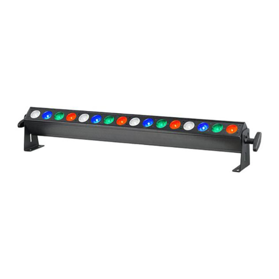
◇ Power Voltage: AC 100V~240V, 50/60Hz ◇ Power Consumption: 163W ◇ Light Source: 16 x 8W RGBW LED ◇ Beam Angle: 45° ◇ Weight: 6.3Kgs ◇ Dimension: 1005 X 110 X 159mm 1005 3. How To Set The Unit 3.1 Control Panel 3 4 5 6 1.POWER IN: Connect the main power supply. -
Page 6: Main Function
SLAVE Slave Mode SOUND Flashing Sound activation 4.Button: MENU To select the programming functions DOWN To go backward in the selected functions To go forward in the selected functions ENTER To confirm the selected functions 5.Display: To show the various menus and the selected functions. 6. - Page 7 DMX Address Channel Mode Show Mode Slave Mode Сolor Mode Dimmer Speed MENU Sound State Sound Sense Master Slave Blackout Mode Last state Display Inversion White Balnce Auto Test Fixture Temperature Fixture Hours Software Version Reset...
- Page 8 DMX 512 Address Setting Press the MENU button up to when the is shown on the display. Pressing ENTER button and the display will blink. Use DOWN and UP button to change the value. Once the mode has been selected, press the ENTER button to setup, to go back to the functions without any change press the MENU button again.
- Page 9 Color Mode Press the MENU button up to when the is shown on the display. Pressing the ENTER button. Use DOWN and UP button to select the (Color 1) …… (Color 32) mode. Once the mode has been selected, press the ENTER button to setup, to go back to the functions without any change press the MENU button again.
- Page 10 DMX State Press the MENU button up to when the is shown on the display. Pressing ENTER button, Use DOWN and UP button to select the (master slave), (blackout mode) or (last state). Once the mode has been selected, press the ENTER button to setup, to go back to the functions without any change press the MENU button again.
-
Page 11: How To Control The Unit
Auto Test Press the MENU button up to when the is blinking on the display. Press the ENTER button and the unit will run the built-in programmer for self-test. To go back to the functions press the MENU button. Fixture Temperature Press the MENU button up to when the is blinking on the display. -
Page 12: Master/Slave Built In Preprogrammed Function
No need to turn the unit off when you change the DMX address, as new DMX address setting will be affect at once. Every time you turn the unit on, it will show “LED MB200R” on the display and move all the motors to their ‘home’ position and you may hear some noises for about 20 seconds. After that the unit will be ready to receive DMX signal or run the built in programs. -
Page 13: Dmx 512 Configuration
Unit 1 Unit 2 Unit 3 Unit 4 Channel mode Address Address Address Address 1 channels 3 channels 4 channels 7 channels 8 channels 16 channels 32 channels 67 channels 4.3 DMX 512 Configuration 1 CH MODE (MODE 1): CHANNEL VALUE FUNCTION SHOW MODE... - Page 14 3 CH MODE (MODE 2): CHANNEL VALUE FUNCTION 000 – 255 RED: 0% 100% 000 – 255 GREEN: 0% 100% 000 – 255 BLUE: 0% 100% 4 CH MODE (MODE 3): CHANNEL VALUE FUNCTION 000 – 255 RED: 0% ...
- Page 15 000 – 255 DIMMER: 0% 100% COLOR 001-007 Color 1 008-015 Color 2 016-023 Color 3 024-031 Color 4 032-039 Color 5 040-047 Color 6 048-055 Color 7 056-063 Color 8 064-071 Color 9 072-079 Color 10 080-087 Color 11 088-095 Color 12 096-103...
- Page 16 8 CH MODE (MODE 4): CHANNEL VALUE FUNCTION 000 – 255 RED 1: 0% 100% 000 – 255 GREEN 1: 0% 100% 000 – 255 BLUE 1: 0% 100% 000 – 255 WHITE 1: 0% 100% 000 –...
- Page 17 32 CH MODE (MODE 6): CHANNEL VALUE FUNCTION 000 – 255 RED 1: 0% 100% 000 – 255 GREEN 1: 0% 100% 000 – 255 BLUE 1: 0% 100% 000 – 255 WHITE 1: 0% 100% 000 –...
- Page 18 67 CH MODE (MODE 7): CHANNEL VALUE FUNCTION 000 – 255 RED 1: 0% 100% 000 – 255 GREEN 1: 0% 100% 000 – 255 BLUE 1: 0% 100% 000 – 255 WHITE 1: 0% 100% 000 –...
- Page 19 001-007 Color 1 008-015 Color 2 016-023 Color 3 024-031 Color 4 032-039 Color 5 040-047 Color 6 048-055 Color 7 056-063 Color 8 064-071 Color 9 072-079 Color 10 080-087 Color 11 088-095 Color 12 096-103 Color 13 104-111 Color 14 112-119 Color 15...
-
Page 20: Dmx512 Connection
4.4 DMX512 Connection 1. At last unit, the DMX cable has to be terminated with a terminator. Solder a 120-ohm 1/4W resistor between pin 2(DMX-) and pin 3(DMX+) into a 3-pin XLR-plug and plug it in the DMX-output of the last unit. 2. -
Page 21: Troubleshooting
3 pin XLR: Pin 1: GND, Pin 2: Negative signal (-), Pin 3: Positive signal (+) 5 pin XLR: Pin 1: GND, Pin 2: Negative signal (-), Pin 3: Positive signal (+), Pin4, Pin5 not used. 5. Troubleshooting Following are a few common problems that may occur during operation. Here are some suggestions for easy troubleshooting: A. -
Page 22: Fixture Cleaning
1. The stepper motor might be damaged or the cable connected to the PCB is broken. 2. The motor’s drive IC on the PCB might be out of condition. 6. Fixture Cleaning The cleaning must be carried out periodically to optimize light output. Cleaning frequency depends on the environment in which the fixture operates: damp, smoky or particularly dirty surrounding can cause greater accumulation of dirt on the unit’s optics. -
Page 23: Declaration Of Conformity
Declaration of Conformity We declare that our products (lighting equipments) comply with the following specification and bears CE mark in accordance with the provision of the Electromagnetic Compatibility (EMC) Directive 89/336/EEC. EN55103-1: 2009+A1:2012; EN55103-2: 2009; EN61000-3-2: 2014; EN61000-3-3: 2013. & Harmonized Standard EN 60598-1:2015;... - Page 24 Innovation, Quality, Performance...
Need help?
Do you have a question about the CB-16FC and is the answer not in the manual?
Questions and answers