Table of Contents
Advertisement
Quick Links
Advertisement
Table of Contents

Related Manuals for ADLINK Technology NuDAQ cPCI-7248


Summary of Contents for ADLINK Technology NuDAQ cPCI-7248
- Page 1 Artisan Technology Group is your source for quality new and certified-used/pre-owned equipment SERVICE CENTER REPAIRS WE BUY USED EQUIPMENT • FAST SHIPPING AND DELIVERY Experienced engineers and technicians on staff Sell your excess, underutilized, and idle used equipment at our full-service, in-house repair center We also offer credit for buy-backs and trade-ins •...
- Page 2 ® NuDAQ cPCI-7248/7249R PCI-7224/7248/7296 24/48/96-CH Digital I/O Card Users’ Guide Recycled Paper Artisan Technology Group - Quality Instrumentation ... Guaranteed | (888) 88-SOURCE | www.artisantg.com...
- Page 3 Artisan Technology Group - Quality Instrumentation ... Guaranteed | (888) 88-SOURCE | www.artisantg.com...
- Page 4 ©Copyright 1997~2002 ADLINK Technology Inc. All Rights Reserved. Manual Rev. 2.60: April 25, 2003 Part No. 50-11104-201 The information in this document is subject to change without prior notice in order to improve reliability, design and function and does not represent a commitment on the part of the manufacturer.
- Page 5 Getting service from ADLINK Customer Satisfaction is always the most important thing for ADLINK Tech Inc. If you need any help or service, please contact us and get it. ADLINK Technology Inc. Web Site http://www.adlinktech.com Sales & Service service@adlinktech.com NuDAQ nudaq@adlinktech.com...
-
Page 6: Table Of Contents
Table of Contents Introduction................1 Features .................2 1.1.1 Digital I/O Ports ................2 1.1.2 Timer/Counter and Interrupt System..........2 1.1.3 Miscellaneous ...................2 Applications ................2 Specifications .................3 Software Supporting...............4 1.4.1 Programming Library ................4 ® 1.4.2 PCIS-LVIEW: LabVIEW Driver ............5 1.4.3 PCIS-VEE: HP-VEE Driver ...............5 1.4.4 DAQBench : ActiveX Controls............5 1.4.5 DASYLab... - Page 7 Registers Format ..............20 PCI PnP Registers ...............20 I/O Address Map ..............21 Operation Theorem..............22 Digital I/O Ports ..............22 4.1.1 Introduction..................22 4.1.2 8255 Mode 0...................22 4.1.3 Special Function of the DIO Signals ..........22 4.1.4 Digital I/O Port Programming ............23 4.1.5 Control Word ..................23 4.1.6 Power on Configuration ..............24 4.1.7 Note for Output Data...............24 4.1.8 Note for cPCI-7249R ..............24...
- Page 8 5.14 Clear IRQ................45 5.15 Software Reset..............45 5.16 Interrupt Start under Windows ..........46 5.17 Interrupt Stop under Windows..........47 Warranty Policy................48 Table of Contents • iii Artisan Technology Group - Quality Instrumentation ... Guaranteed | (888) 88-SOURCE | www.artisantg.com...
- Page 9 How to Use This Guide This manual is designed to help you use the 7248/96 series products. It describes how to modify and control various functions on the cards to meet your requirements. It is divided into five chapters: Chapter 1, Introduction, gives an overview of the product features. applications, and specifications.
-
Page 10: Introduction
Introduction The 7248/7296 series products are general purpose digital I/O cards. This series includes four cards: PCI-7224: 24-CH DIO card PCI-7248: 48-CH DIO card PCI-7296: 96-CH DIO card cPCI-7248: 3U CompactPCI 48-CH DIO card cPCI-7249R: 3U CompactPCI 48-CH DIO card with Rear I/O The 7248 series products are multi-function digital I/O boards used for industrial PC with PCI bus or CompactPCI bus. -
Page 11: Features
Features The 7248/96 series products provide the following advanced features: 1.1.1 Digital I/O Ports 24/ 48/96 TTL/DTL compatible digital I/O lines Emulates industry standard mode 0 of 8255 PPI Buffered circuits for higher driving Direct interface with OPTO-22 compatible I/O module Output status read-back 1.1.2 Timer/Counter and Interrupt System A 32 bits timer to generate watchdog timer interrupt... -
Page 12: Specifications
Specifications I/O channels 24-bit for PCI-7224 48-bit for PCI-7248 96-bit for PCI-7296 48-bit for cPCI-7248 and cPCI-7249R Digital Input Signal Logic High Voltage:2.0 V to 5.25V Logic Low Voltage: 0.0 V to 0.80V Logic High Current: 20.0 uA Logic Low Current: -0.2 mA Digital Output Signal Logic High Voltage: Minimum 2.4 V Logic Low Voltage: Maximum 0.5V... -
Page 13: Software Supporting
Software Supporting ADLINK provides versatile software drivers and packages for users’ different approach to built-up a system. We not only provide programming library such as DLL for many Windows systems, but also provide drivers for many ® software package such as LabVIEW , HP VEE , DASYLab , InTouch... -
Page 14: Pcis-Lview: Labview ® Driver
® 1.4.2 PCIS-LVIEW: LabVIEW Driver PCIS-LVIEW contains the VIs, which are used to interface with NI’s ® LabVIEW software package. PCIS-LVIEW supports Windows ® 95/98/NT/2000. The LabVIEW drivers are free shipped with the board. You can install and use them without license. For detail information about PCIS- LVIEW, please refer to the user’s guide in the CD. -
Page 15: Pcis-Isg: Isagraf
1.4.7 PCIS-ISG: ISaGRAF driver The ISaGRAF WorkBench is an IEC1131-3 SoftPLC control program development environment. The PCIS-ISG includes ADLink products’ target drivers for ISaGRAF under Windows NT environment. The PCIS-ISG is included in the ADLINK CD. It needs license. 1.4.8 PCIS-ICL: InControl Driver PCIS-ICL is the InControl driver which support the Windows NT. -
Page 16: Installation
Installation This chapter describes how to install the 7248/96 series products. At first, the contents in the package and unpacking information that you should be careful of are described. Check what you have (section 2.1) Unpacking (section 2.2) Check the PCB (section 2.3) Hardware installation (section 2.4) Device Installation for Windows System (section 2.5) Connector pin assignment (section 2.6) -
Page 17: Unpacking
Unpacking Your card contains sensitive electronic components that can be easily damaged by static electricity. The card should be put on a grounded anti-static mat. The operator should wear an anti-static wristband, grounded at the same point as the anti-static mat. -
Page 18: Pcb Layout
PCB Layout 2.3.1 PCI-7248/7224 PCB Layout Figure 2.3.1 PCI-7248/7224 PCB Layout 2.3.2 PCI-7296 PCB Layout Controller CN 1 CN 2 CN 3 CN 4 Figure 2.3.2 PCI-7296 PCB Layout Installation • 9 Artisan Technology Group - Quality Instrumentation ... Guaranteed | (888) 88-SOURCE | www.artisantg.com... -
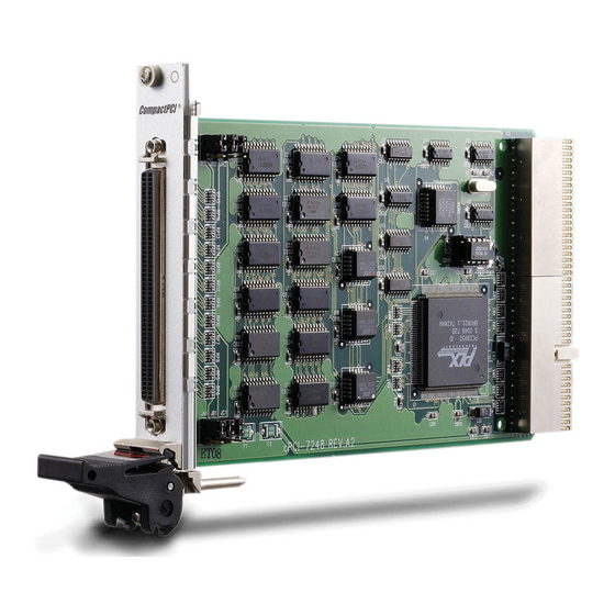
Page 19: Cpci-7248 Pcb Layout
2.3.3 cPCI-7248 PCB Layout CPCI-7248 JC2 JB2 JA2 PCI Controller Chip JA1 JB1 JC1 Figure 2.3.3 cPCI-7248 PCB Layout 2.3.4 cPCI-7249R PCB Layout Figure 2.3.4 cPCI-7249R Layout 10 • Installation Artisan Technology Group - Quality Instrumentation ... Guaranteed | (888) 88-SOURCE | www.artisantg.com... -
Page 20: Hardware Installation
Hardware Installation PCI configuration The PCI cards (or CompactPCI cards) are equipped with plug and play PCI controller, it can request base addresses and interrupt according to PCI standard. The system BIOS will install the system resource based on the PCI cards’... -
Page 21: Device Installation For Windows Systems
CompactPCI Installation Procedures 1. Read through this manual, and setup the jumper according to your application. 2. Turn off your computer and turn off all accessories connected to computer. 3. Remove the slot cover from the CompactPCI. 4. Select a 32-bit CompactPCI slot on the back plane for cPCI-7248 board. Select a 32-bit CompactPCI slot with rear I/O extension for cPCI-7249R. -
Page 22: Connector Pin Assignment
Connector Pin Assignment 2.6.1 Pin Assignment of PCI-7224/7248/7296 The I/O ports of PCI-7224/7248/7296 emulate the mode 0 configuration of the 8255 general purpose programmable peripheral interface. The cards come equipped with 50-pin male IDC connectors that interface with OPTO-22. Figure 2.4 shows the circuits and pinout of PCI-7224/7248/7296's connectors (CN1~CN4) . -
Page 23: Pin Assignment Of Cpci-7248
2.6.2 Pin Assignment of cPCI-7248 The cPCI-7248 is equipped a SCSI-type 100-pin connector. The pin assignment is described in Figure 2.6.2 (51) (1) P1A0 (26) P2A0 (51) EVENT (76) GND (52) (2) P1A1 (27) P2A1 (52) GND (77) GND (53) (3) P1A2 (28) P2A2 (53) GND... -
Page 24: Pin Assignment Of Cpci-7249R
2.6.3 Pin Assignment of cPCI-7249R The I/O ports of cPCI-7249R emulate the mode 0 configuration of the 8255 general purpose programmable peripheral interface. This card comes equipped with SCSI -100 Pin connector. And the cPCI-7249R supports R7249 daughter board for rear I/O, it includes two OPTO-22 connectors and one SCSI -100 connector. -
Page 25: R7249 Opto-22 Connectors
2.6.4 R7249 OPTO-22 Connectors The cPCI-7249R’s rear I/O transition board R7249 is equipped with two 50 pin male IDC connectors XCN2, XCN3, that interface with OPTO-22. Figure 2.3 R7249 OPTO-22 Connectors Pin Assignment Note : The power supply pins are protected by resetable fuses. Refer to section 3.7 for details of the power supply. -
Page 26: Jumpers Description
Jumpers Description The 7248/96 DIO cards are ‘plug-and-play’, thus it is not necessary to setup the card configurations to fit the computer system. However, to fit users’ versatile operation environment, there are still a few jumpers to set the power-on status of ports and the usage of the +12V output pins. 2.7.1 Power on Status of Ports For every port on the 7248/96 cards, the power-on status is set as input, therefore, the voltage could be pulled high, pulled low, or floating. -
Page 27: Power Supply Configuration
2.7.2 12V Power Supply Configuration The pin 2 and pin 4 of the CN1 ~ CN4 50-pin OPTO-22 connectors can be configured as 12V power supply or ground. Please refer to Figure 2.4 for the 12 volts power supply position. JP1~JP4 of the 12V power are for CN1~CN4 respectively. - Page 28 3. TB-16P8R The TB-16P8R provides 16 opto-isolated digital input channels and 8 relay outputs. P C I- 7 2 9 6 T B - 1 6 P 8 R P C I- 7 2 4 8 4. TB-24, DIN-50S TB-24 and DIN-50S are termination boards with 50 pin ribbon connector. They are used for general-purpose applications.
-
Page 29: Registers Format
Registers Format The detailed descriptions of the registers format are specified in this chapter. This information is quite useful for the programmers who wish to handle the card by low-level programming. However, we suggest user have to understand more about the PCI interface then start any low-level programming. -
Page 30: I/O Address Map
I/O Address Map All the 724X registers are 8 bits. The users can access these registers only by 8 bits I/O instructions. The following table shows the registers map, including descriptions and their offset addresses relative to the base address. Please refer to the chapter 4 for more detailed operation of every registers. -
Page 31: Operation Theorem
Operation Theorem Digital I/O Ports 4.1.1 Introduction The 7248/96 products can emulate one/two/four mode 0 configuration of 8255 programmable peripheral interface (PPI) chips. There are 24 DIO signals for every PPI. 4.1.2 8255 Mode 0 The basic functions of 8255 mode 0 are: Two 8-bit I/O ports−−port A (PA) and port B (PB) Two nibble-wide (4-bit) ports C−−PC upper and PC lower Each port can be used as either input or output... -
Page 32: Digital I/O Port Programming
4.1.4 Digital I/O Port Programming Users can write the digital output value to or read back the digital signal level from the PPI ports by using the software library. Here we define the port name in Table 4.1. These port names are used both in software library and all through this manual. -
Page 33: Power On Configuration
Control PORT PORT C PORT PORT C Word UPPER LOWER 1BH* Table 4.2 Summary of control word (D0 - D4) (* power on default configuration) 4.1.6 Power on Configuration The default configuration after power on, hardware reset or software reset sets all ports as input ports, therefore the users don’t have to worry about damaging the external devices when system is power on. -
Page 34: Timer/Counter Operation
Timer/Counter Operation 4.2.1 Introduction One 8254 programmable timer/counter chip is installed in 7248/96 series. There are three counters in one 8254 chip and 6 possible operation modes for each counter. The block diagram of the timer /counter system is shown in Figure 4.2. -
Page 35: Cascaded 32 Bits Timer
The 8254 timer/ counter IC occupies 4 I/O address. Users can refer to Tundra's or Intel's data sheet for a full description of the 8254 features. You can download the 8254 data sheet from the following web site: http://support.intel.com/support/controllers/peripheral/231164.htm http://www.tundra.com (for Tundra’s 82C54 datasheet.) 4.2.2 Cascaded 32 Bits Timer The input clock frequency of the cascaded timers is 2MHz. -
Page 36: Irq Level Setting
4.3.2 IRQ Level Setting There is only one IRQ level requested by this card, although it is a dual interrupt system. The mother board circuits will transfer INTA# to one of the PC IRQ levels. The IRQ level is set by the PCI plug and play BIOS and saved in the PCI controller. -
Page 37: Interrupt Source Control
4.3.4 Interrupt Source Control In ISC register (offset 0x20), there are four bits to control the IRQ sources of INT1 and INT2. If the application need only one IRQ, you can disable one of the IRQ sources by software. If your application do not need any IRQ source, you can disable both interrupts. -
Page 38: And 5V Power Supply
12V and 5V Power Supply The OPTO-22 compatible connectors provide external devices the +12 volts and +5 volts power supply. To avoid short or overload of the power supply, the resetable fuses are added on all the output power. Refer to Figure 2.6.1 The maximum current for 5 volts on every connector is 0.5 A. -
Page 39: C/C++ Libraries
C/C++ Libraries This chapter describes the software library for operating these card. Only the functions in DOS library and Windows 95 DLL are described. Please refer to the PCIS-DASK function reference manual, which included in ADLINK CD, for the descriptions of the Windows 98/NT/2000 DLL functions. The functions of PCI-7248 can also be applied to PCI-7224 and cPCI-7248. -
Page 40: Programming Guide
Programming Guide 5.2.1 Naming Convention The functions of the NuDAQ PCI cards or NuIPC CompactPCI cards’ software driver are using full-names to represent the functions' real meaning. The naming convention rules are: In DOS Environment: _{hardware_model}_{action_name}. e.g. _7248_Initial() . All functions in PCI-7248 driver are with 7248 as {hardware_model}. But they can be used by PCI-7248, PCI-7224 and cPCI-7248. -
Page 41: 7248/96_Initial
_7248/96_Initial @ Description The cards are initialized by this function. The software library could be used to control multiple cards. @ Syntax C/C++ (DOS) _7248_Initial (U16 *existCards, PCI_INFO *pciInfo) _7249_Initial (U16 *existCards, PCI_INFO *pciInfo) _7296_Initial (U16 *existCards, PCI_INFO *pciInfo) C/C++ (Windows 95) W_7248_Initial (U16 *existCards, PCI_INFO *pciInfo) W_7249_Initial (U16 *existCards, PCI_INFO *pciInfo) W_7296_Initial (U16 *existCards, PCI_INFO *pciInfo) -
Page 42: Digital Input
Digital Input @ Description This function is used to read 8-bit digital input data from digital input ports. You can get the 8-bit data from _7248_DI by using this function. The written data and read in data is 8-bit data. Each data is mapped to a signal as the table below. - Page 43 PCI_CH2_PCU: CH2’s Port C Upper Nibble PCI_CH2_PCL: CH2’s Port C Low Nibble PCI_CH3_PA: CH3’s Port A PCI_CH3_PB: CH3’s Port B PCI_CH3_PC: CH3’s Port C PCI_CH3_PCU: CH3’s Port C Upper Nibble PCI_CH3_PCL: CH3’s Port C Low Nibble PCI_CH0_PAE: CH1’s Port A uses External Latch PCI_CH0_PBE: CH1’s Port B uses External Latch PCI_CH0_PCE: CH1’s Port C uses External Latch PCI_CH1_PAE: CH2’s Port A uses External Latch...
-
Page 44: Digital Output
Digital Output @ Description This function is used to write data to digital output ports. @ Syntax C/C++ (DOS) _7248_DO (U16 cardNo, U16 channelPort, U8 doData) _7249_DO (U16 cardNo, U16 channelPort, U8 doData) _7296_DO (U16 cardNo, U16 channelPort, U8 doData) C/C++ (Windows 95) W_7248_DO (U16 cardNo, U16 channelPort, U16 doData) W_7249_DO (U16 cardNo, U16 channelPort, U16 doData) -
Page 45: Configuration Port
Configuration Port @ Description This function is used to configure the Input or Output of each Port. Each I/O Port of PCI-7224/7248/7296 is either input or output, so it has to configure as input or output before I/O operations are applied. @ Syntax C/C++ (DOS) _7248_Config_Port (U16 cardNo, U16 channelPort,... -
Page 46: Configuration Channel
Configuration Channel @ Description This function is used to configure the Input or Output of each Channel. Each I/O Port of PCI-7224/7248/7296 is either input or output, so it has to configure as input or output before I/O operations are applied. @ Syntax C/C++ (DOS) _7248_Config_Channel (U16 cardNo, U16 channelNo,... - Page 47 ctrlValue Port A Port CU Port B Port CL PORT_OOOO OUT PORT_OOOI OUT PORT_OOIO OUT PORT_OOII OUT PORT_OIOO OUT PORT_OIOI OUT PORT_OIIO OUT PORT_OIII OUT PORT_IOOO IN PORT_IOOI IN PORT_IOIO IN PORT_IOII IN PORT_IIOO IN PORT_IIOI IN PORT_IIIO IN PORT_IIII IN The ctrlValue constants are defined in acl_pci.h and acl_pci.bas.
-
Page 48: Set Interrupt Control
Set Interrupt Control @ Description This function is used to set the interrupt configuration. The interrupt should be configured before the function starts. @ Syntax C/C++ (DOS) void _7248_Set_INT_Control(U16 cardNo, U16 ctrlValue); void _7249_Set_INT_Control(U16 cardNo, U16 ctrlValue); void _7296_Set_INT_Control(U16 cardNo, U16 ctrlValue); C/C++ (Windows 95) void W_7248_Set_INT_Control(U16 cardNo, U16 ctrlValue);... -
Page 49: Timer Start
Timer Start @ Description This function is used to set and start the timer0 of the on-board timer 8254 . @ Syntax C/C++ (DOS) void _7248_Timer_Start(U16 cardNo, U16 timer0Mode, U16 c0) void _7249_Timer_Start(U16 cardNo, U16 timer0Mode, U16 c0) void _7296_Timer_Start(U16 cardNo, U16 timer0Mode, U16 c0) C/C++ (Windows 95) void W_7248_Timer_Start(U16 cardNo, U16 timer0Mode,... -
Page 50: Timer Read
5.10 Timer Read @ Description This function is used to read the current count of the timer0 of the on- board timer 8254 . @ Syntax PCI-7224/7248, CPCI-7248: C/C++ (DOS) void _7248_Timer_Read(U16 cardNo, U16 *counterValue); void _7249_Timer_Read(U16 cardNo, U16 *counterValue); void _7296_Timer_Read(U16 cardNo, U16 *counterValue);... -
Page 51: Timer Stop
5.11 Timer Stop @ Description This function is used to stop the timer0 of the on-board timer 8254 . @ Syntax C/C++ (DOS) void _7248_Timer_Stop(U16 cardNo, U16 *counterValue); void _7249_Timer_Stop(U16 cardNo, U16 *counterValue); void _7296_Timer_Stop(U16 cardNo, U16 *counterValue); C/C++ (Windows 95) void W_7248_Timer_Stop(U16 cardNo, U16 *counterValue);... -
Page 52: Cascaded Timer
5.12 Cascaded Timer @ Description This function is used to set and start the cascaded timer1 and timer 2 of the on- board timer 8254 . @ Syntax C/C++ (DOS) void _7248_Cascaded_Timer(U16 cardNo, U16 c1, U16 c2); void _7249_Cascaded_Timer(U16 cardNo, U16 c1, U16 c2); void _7296_Cascaded_Timer(U16 cardNo, U16 c1, U16 c2);... -
Page 53: Get Irq Status
5.13 Get IRQ Status @ Description This function is used to read back the status of interrupt when interrupt is inserted. @ Syntax C/C++ (DOS) void _7248_Get_IRQ_Status(U16 cardNo, U16 *int1Status, U16 *int2Status); void _7249_Get_IRQ_Status(U16 cardNo, U16 *int1Status, U16 *int2Status); void _7296_Get_IRQ_Status(U16 cardNo, U16 *int1Status, U16 *int2Status);... -
Page 54: Clear Irq
5.14 Clear IRQ @ Description This function is used to clear the interrupt generated from the 7248/96 series. @ Syntax C/C++ (DOS) void _7248_CLR_IRQ(U16 cardNo); void _7249_CLR_IRQ(U16 cardNo); void _7296_CLR_IRQ(U16 cardNo); C/C++ (Windows 95) void W_7248_CLR_IRQ(U16 cardNo); void W_7249_CLR_IRQ(U16 cardNo); void W_7296_CLR_IRQ(U16 cardNo);... -
Page 55: Interrupt Start Under Windows
Visual Basic (Windows 95) W_7248_Software_Reset (ByVal cardNo As Integer) As Integer W_7249_Software_Reset (ByVal cardNo As Integer) As Integer W_7296_Software_Reset (ByVal cardNo As Integer) As Integer @ Argument cardNo: card number which the DIO will be reset. @ Return Code ERR_NoError 5.16 Interrupt Start under Windows @ Description This function is only available in Windows 95/98 driver. -
Page 56: Interrupt Stop Under Windows
@ Argument cardNo: card number which the DIO will be reset. If the interrupt source is set as internal timer source, this value is the frequency divider of Timer#1. If the interrupt source is set as internal timer source, this value is the frequency divider of Timer#2. -
Page 57: Warranty Policy
Warranty Policy Thank you for choosing ADLINK. To understand your rights and enjoy all the after-sales services we offer, please read the following carefully. Before using ADLINK’s products please read the user manual and follow the instructions exactly. When sending in damaged products for repair, please attach an RMA application form which can be downloaded from: http://rma.adlinktech.com/policy/. - Page 58 • Damage caused by inappropriate storage environments such as with high temperatures, high humidity, or volatile chemicals. • Damage caused by leakage of battery fluid during or after change of batteries by customer/user. • Damage from improper repair unauthorized ADLINK technicians.
- Page 59 Artisan Technology Group is your source for quality new and certified-used/pre-owned equipment SERVICE CENTER REPAIRS WE BUY USED EQUIPMENT • FAST SHIPPING AND DELIVERY Experienced engineers and technicians on staff Sell your excess, underutilized, and idle used equipment at our full-service, in-house repair center We also offer credit for buy-backs and trade-ins •...
Need help?
Do you have a question about the NuDAQ cPCI-7248 and is the answer not in the manual?
Questions and answers