Advertisement
Quick Links
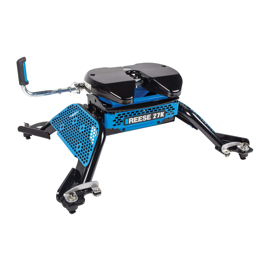
FOR INSTALLATION WITH
M5 MOUNTING LEGS
WARNING: Failure to follow installation and hitch-up instructions may cause property loss, serious injury, or death!
CAUTION: Under no circumstances do we recommend exceeding the towing vehicle manufacturers recommended vehicle
READ ALL INSTRUCTIONS BEFORE STARTING THE INSTALLATION
Equipment Required:
M13 Socket
Torque Wrench
Lithium Grease
2
6
7
3
4
Installation
- Assembly
- Added clearance to Cab
- Guidelines for matching hitch,
truck, and trailer
Use Instructions
*Note: Leg Assembly instructions can be found under their individual part number
Installation Instructions
M5 HEAD & CENTER SECTION
Hitch Rated for 20,000 lbs.
Max. Pin Weight 5,000 lbs.
towing and load capacity
NOTE: It is recommended that you start with the M5 Leg Instructions.
1
5
8
Legs (Sold Separately)
(GM shown)
Table of Contents
p 2
p 2
p 3
p 4
p 7
.
VEHICLE FORWARD
FIG. 1
- Handle Position Overview
- Hitching
- Pull Test
- Unhitching
- Maintenance
Part Number:
30892 & 30884
#
1
M5 Head Unit
(30892)
2
Handle
3
½" Pull Pin
4
Spring Clip
4
5
M8 Carriage Bolt
6
M8 Lock Washer
3
7
M8 Nut
8
M5 Center
Section (30884)
Description
Qty.
1
1
2
2
2
2
2
1
p 7
p 8
p 8
p 9
p 10
Advertisement

Related Manuals for Reese M5


Summary of Contents for Reese M5
- Page 1 CAUTION: Under no circumstances do we recommend exceeding the towing vehicle manufacturers recommended vehicle towing and load capacity READ ALL INSTRUCTIONS BEFORE STARTING THE INSTALLATION Equipment Required: NOTE: It is recommended that you start with the M5 Leg Instructions. M13 Socket Torque Wrench Lithium Grease Description Qty.
- Page 2 Center Section Attachment to Legs 1. Fasteners and assembly instructions are included with the M5 Leg Structure, sold separately. 2. For height adjustment, the unit should be set to have a minimum of 6” clearance between the truck bed rail and the bottom of the trailer.
-
Page 3: Pinch Point Areas
Installation Instructions Part Number: M5 HEAD & CENTER SECTION 30892 & 30884 FOR INSTALLATION WITH M5 MOUNTING LEGS TO INCREASE THE GAP BETWEEN TRAILER AND TRUCK CAB by 1-1/2”. The center section has an option to increase the gap between the trailer front and the truck cab by 1-1/2” by rotating the center section 180 degrees. -
Page 4: Fig
*Trailer weight should be the lowest of these recorded ratings for safe towing conditions. 2. Reese hitches are designed for use with recreational fifth wheel trailers only. 3. Use only a SAE 2-inch king pin with your M-Series Fifth Wheel Hitch. -
Page 5: Fig
TRUCK 6. If a short bed pickup (less than 8 ft. but longer than 6 ft.) is to be used for towing, Reese recommends the trailer be equipped with a minimum 13” extended pin box to help gain additional truck - trailer turning clearance (See trailer manufacturer for options) (See Fig. - Page 6 Wheel it must be at least 12” in diameter and not more than 3/16” If a lube plate is to be used with an Elite Series 5 thick. Reese offers this optional lube plate as part # 83001. WARNING: •Connection for trailer wiring must be located at the side of the truck bed between the driver’s seat and the rear wheel to prevent operators from working between the truck and trailer.
- Page 7 Installation Instructions Part Number: M5 HEAD & CENTER SECTION 30892 & 30884 FOR INSTALLATION WITH M5 MOUNTING LEGS HANDLE POSITION OVERVIEW Ready-to-Receive Position: When will the head be in this position? - When delivered - When hitch not in use...
- Page 8 Installation Instructions Part Number: M5 HEAD & CENTER SECTION 30892 & 30884 FOR INSTALLATION WITH M5 MOUNTING LEGS HITCHING PROCEDURE Before hitching to a trailer, make sure your 5 wheel hitch height is correct. Guidelines on how to properly set the height of your 5 wheel hitch can be found in the on page 5.
- Page 9 Installation Instructions Part Number: M5 HEAD & CENTER SECTION 30892 & 30884 FOR INSTALLATION WITH M5 MOUNTING LEGS POTENTIAL LOCK DIMENSIONS 3/4” or greater Ø 5/16” or less 1-1/2” or greater Unhitching Procedure WARNING: Failure to follow these instructions may result in property damage, serious injury, or death.
- Page 10 Installation Instructions Part Number: M5 HEAD & CENTER SECTION 30892 & 30884 FOR INSTALLATION WITH M5 MOUNTING LEGS MAINTENANCE This unit is designed to need very little maintenance and be one of the quietest on the market. In order to ensure long term performance, it is recommended to lubricate as indicated below;...
Need help?
Do you have a question about the M5 and is the answer not in the manual?
Questions and answers