
Related Manuals for Eltek MultiCharger 1500

Summary of Contents for Eltek MultiCharger 1500
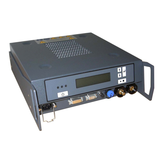
- Page 1 Description and Operating Instructions 2280073 Rev.1 MultiCharger 1500 12V/100A...24V/50A 12V/100A Lithium-ion and Lead-acid Batteries 24V/50A Lead-acid Batteries Read operating instructions carefully before use!
- Page 2 Information provided in this document is subject to the right of change without prior notice and does not represent properties which are guaranteed by Eltek. This document or parts of it may not be reproduced, copied or made accessible to third parties without prior written consent from ELTEK.
-
Page 3: Table Of Contents
Contents Page Competent person Normal use Misuse Fundamental safety instructions Safety symbols used General safety instructions Construction of the charger unit General mode of operation Connections 3.2.1 9-pole SUB-D socket 3.2.2 15-pole SUB-D socket Displays and operating controls 3.3.1 Control button 1 (on/off) 3.3.2 Control button 2 (start/stop) 3.3.3... - Page 4 Page Operating modes (temporary settings) Setting of operating modes Charging mode for lithium-ion batteries, temporary Charging mode for lead-acid batteries, temporary Refresh (if disconnecting switch of the lithium-ion battery is open) Shutdown (only possible in the charging mode for lithium-ion batteries) Internal monitoring Mains power monitoring Monitoring of intermediate-circuit voltage...
- Page 5 Page 10.4 Set voltage limits 10.4.1 Set Ua max. 12V 10.4.2 Set Ua min. 12V 10.4.3 Set Ua max. 24V 10.4.4 Set Ua min. 24V 10.5 Output-current limits (I-limits) 10.5.1 Set I-limit CHRG12V 10.5.2 Set I-limit CHRG24V 10.5.3 Set I-limit EPS 12V 10.5.4 Set I-limit EPS 24V 10.6...
-
Page 6: Use
A person is regarded as competent person if he/she is assigned as instructed to perform particular works on or with the MultiCharger. 1.2 Normal use The MultiCharger 1500 (referred to below as MC1500) is intended for charging vehicle batteries: lead-acid batteries with a nominal voltage of 12 V or 24 V ... -
Page 7: Fundamental Safety Instructions
Fundamental safety instructions Fundamental safety instructions The following fundamental safety instructions are to be understood as supplement to applicable national occupational safety regulations. This means that, next to these fundamental safety instructions, the applicable national occupational safety regulations shall be observed in any case. -
Page 8: General Safety Instructions
Fundamental safety instructions 2.2 General safety instructions In order to charge a battery outside of the vehicle, connect the positive (plus) and the negative (minus) cables in accordance with polarity (see section 5). For a battery installed in the vehicle, first connect the red charging cable of the charger to the positive terminal (+) of the battery (not connected with the chassis) according to the polarity indications and then the black charging cable to the negative terminal (–) of the battery. - Page 9 Fundamental safety instructions Danger! Serious or fatal injuries and/or damage to the charger unit Explanation: During operation in moving vehicles, equipment is not sufficiently safeguarded. It is possible that cables are torn off (spark generation) or that the battery tips over (damaging) Avoidance measures: Do not operate charger unit in moving vehicles Danger!
- Page 10 Fundamental safety instructions 2280073 Rev.1 Page 10...
- Page 11 Fundamental safety instructions Danger! Risk of injury due to electric shock Explanation: There is a risk of electric shock when touching non-isolated parts of the contacts and non-isolated battery clamps. Avoidance measures: Avoid touching any non-isolated parts of the contacts and non-isolated battery clamps.
- Page 12 Fundamental safety instructions Danger! Risk of injury due to electric shock Explanation: There is a risk of electric shock if actions (cleaning, maintenance, repair) are executed on the charger unit while the power cord is connected. Avoidance measures: Disconnect leads before working on the charger unit. Warning! Equipment damage or failure possible! Explanation:...
-
Page 13: Construction Of The Charger Unit
Construction of the charger unit Construction of the charger unit 3.1 General mode of operation The MC1500 is used for charging motor vehicle batteries and can also be used as an external power supply for vehicles. The charger unit is designed for the usage in 12V systems with lithium-ion and lead-acid batteries as well as in 24V systems with lead-acid batteries. -
Page 14: Connections
Construction of the charger unit 3.2 Connections All connections of the MC1500 are on the front. Mains voltage is connected to the MC1500 through an inlet connector for non-heating appliances. 3 potential-free relay contacts which signal various states of the MC1500 as well as a hardware contact "Remote On/Off"... -
Page 15: 9-Pole Sub-D Socket
Construction of the charger unit 3.2.1 9-pole SUB-D socket A 9-pole SUB-D socket on the front side of the charger unit is used to connect a signal light. The signal light (green/yellow/blue/red) indicates the following states of the MultiCharger: Signal light – LED colours State yellow grün... -
Page 16: Displays And Operating Controls
Construction of the charger unit 3.3 Displays and operating controls 3.3.1 Control button 1 (on/off) Control button 1 is used to switch the M1500 on and off. If the connected supply voltage is over 90V, pressing button 1 switches the MultiCharger on and makes it ready for use. Furthermore, pressing button 1 is required to deactivate the interlock after a fault-induced shut- down. -
Page 17: Usb Interface
3.3.6 USB interface A Mini USB socket is fitted on the front side of the charger unit which can be used to connect a laptop or PC. The MC1500 can be configured through this interface and software updates can be carried out. To configure or alter the device software (Firmware Update), the software WinCharge is required. -
Page 18: Setting Of Cable (Wire) Resistance
Setting of cable (wire) resistance Setting of cable (wire) resistance The new software version of the MC1500 includes a cable (resistance) compensation to compensate for voltage drop at the connecting cables of the battery. 4.1 Standard battery-connecting cables In the delivery condition, a cable resistance of 15 mΩ is preset. This applies for a 5 meter/16 mm²... -
Page 19: Charging Process
Charging process Charging process Carefully read and observe the safety instructions given in section 2 as well as the instructions of the respective battery manufacturer concerning safety and charging current. 5.1 Positioning of the MultiCharger Position the charger unit as far away from the battery as possible, make use of the entire cable length of the connected charging cable and check for (static) stability Do not place the MultiCharger directly on top of the battery Avoid dripping of acid onto the charger unit. -
Page 20: Charging Of A Battery Outside The Vehicle
Charging process 5.4 Charging of a battery outside the vehicle Connect to the power supply and connect charging cable to the charger unit. Check polarity of battery terminals. The diameter of the positive battery terminal (POS, P, ) is usually larger than that of the negative terminal (NEG, N, ). First, connect the NEGATIVE (BLACK) clamp of the charging cable supplied with the charger to the NEGATIVE (NEG, N, -) terminal. -
Page 21: Operating Modes/Charging Mode (Permanent Settings)
Operating modes/charging mode (permanent settings) Operating modes/charging mode (permanent settings) 6.1 Setting of operating modes Setting operating mode is only possible if the MC1500 is ready for use, i.e. if it has been switched on via button 1 (On/Off). However, there shall no activated charging procedure and no battery connected to the charger's output. -
Page 22: Charging Agm Batteries
Operating modes/charging mode (permanent settings) 6.3 Charging AGM batteries It is possible that the batteries used in some vehicles may be so-called AGM (Absorbent Glass Mat) batteries, i.e. batteries containing an absorbent glass-fiber mat. These batteries require special attention. The charging voltage must never exceed 14.8V (or 29.6V for 24V batteries). -
Page 23: Charging Mode For 12V Lithium-Ion Batteries (Charging Lio)
Hence, the charging cycle starts again. If, during an adjustable time (default setting 12h), the charging current doesn't fall below 2.5A, the MultiCharger 1500 is switched over to trickle charging and status message "Max. CHRG time" is shown on the display. -
Page 24: Output Voltage In Battery Charging Mode
The charging process can also be stopped at any time by pressing button 1 (On/Off). When the MultiCharger 1500 is switched back on, the charging process would then begin again from the start. 6.7.2 Output current in battery charging mode In the battery charging mode, the MC1500 can be briefly (max. -
Page 25: Eps Mode
Operating modes/charging mode (permanent settings) 6.8 EPS mode This operating mode enables power to be supplied to vehicles that have no battery. Once the MC1500 has been switched on by pressing control button 1 (On/Off), it is ready for use. That means that the MC1500’s output voltage will stay at zero volts until button 2 (Start/Stop) is pressed. -
Page 26: Operating Modes (Temporary Settings)
Operating modes (temporary settings) Operating modes (temporary settings) 7.1 Setting of operating modes Several operating modes can be temporarily set. This temporary setting is possible without entering any password and applies for one charging cycle only. Installed batteries as well as batteries removed from the vehicle can be charged using the functions described in 7.2 to 7.4. -
Page 27: Refresh (If Disconnecting Switch Of The Lithium-Ion Battery Is Open)
Operating modes (temporary settings) 7.4 Refresh (if disconnecting switch of the lithium-ion battery is open) The lithium-ion battery is equipped with a disconnecting switch to protect the battery against e.g. exhaustive discharge. In the case of an error, the disconnecting switch opens and isolates the battery from the load. -
Page 28: Internal Monitoring
Internal monitoring Internal monitoring The MC1500 has several internal monitoring functions that ensure safe operation. These functions are individually described in the following sub-sections. 8.1 Mains power monitoring If the supply voltage drops below 85V, the MultiCharger signals a fault and switches off. The message "Mains error"... -
Page 29: Output Overcurrent
Internal monitoring 8.5 Output overcurrent If, due to an internal fault in the charger unit, the output current exceeds the prevailing current- limit level by more than 25%, the MC1500 signals a fault and switches off to the locked position. The message "Overcurrent"... -
Page 30: External Monitoring
External monitoring External monitoring The MC1500 has a number of external monitoring functions that keep a constant check on connected power consumers. These functions are individually described in the following sub- sections. 9.1 Short circuit The MC1500 can detect an output short circuit if this occurs in the current limiter and if the output voltage falls below the set lower limit (default setting 7V or 14V). -
Page 31: Return Voltage With Reversed Polarity
External monitoring 9.6 Return voltage with reversed polarity This monitoring function is only active in EPS mode (see section 6.8). It is not permitted to connect a battery to the MC1500 in this operating mode. If, in spite of that, a battery is connected with reverse polarity prior charging, the charger unit signals a fault. -
Page 32: Service Menu
Service menu Service menu The service menu is used to make basic system settings at the MC1500. The structure of this menu is set out below. To avoid mistakes, these settings are protected by a code which should be given access only to properly trained persons. The code for using the service menu is: 0109: Modification of parameters such as charging voltage, current limits, monitoring limits and process times must be made appropriately. - Page 33 Service menu Structure of service menu U=00.0V I=0.0A Service menu Pb no contact code:0000 Present mode Activate Set voltage Set voltage limit Charging Pb mode 24V mode Present mode Charging LIO Present mode 24V mode off Set 12V Pb Trickle Pb Set Ua max.12V Ua max.12V Taste...
- Page 34 Service menu Structure of service menu Set wire resistance Set current limit Set process times Turn on/off autostart Set I-limit I-limit CHRG 12V Set switch back Switch back time Wire resistance Autostart CHRG12V Now at: 80A/100A time Now at: 005min Now at: 015mOhm now enabled Set I-limit...
- Page 35 Service menu Structure of service menu Error log Factory settings Software version Select Language Save entries Exit menu MC1xDxx Display error log? Error 9: Load factory Factory settings Sprache aktuell Num. errors = x xxxxxx settings? loaded Deutsch Error 8…1: Current language xxxxxx English...
-
Page 36: Setting Of Operating Modes
Service menu 10.1 Setting of operating modes The ‘Set mode’ menu allows the setting and activation of the different operating modes of the MC1500. These settings should be made very carefully to avoid any potential damage to the vehicle connected to the charger (e.g. connecting a charger in EPS 24V mode to a vehicle with a 12V electrical system will cause damage to the vehicle). -
Page 37: Activate 24V Mode
Service menu 10.2 Activate 24V mode The "Activate 24V mode" menu allows activation or deactivation of all operating modes with 24V nominal voltage. These settings should be made with particular care to ensure that unauthorized use of the charger with 24 V operating voltage is not possible. Such use could cause damage to any vehicle that might be connected to the charger. -
Page 38: Set 12V Pb Charging Voltage
Service menu 10.3.4 Set 12V Pb charging voltage This is a sub-item of the "Set voltage" menu. It is used to set the charging voltage to 12V for the operating mode for charging 12V lead-acid batteries. Default setting: 14.8V Setting range: 9.0V to 16.0V 10.3.5 Set 12V LIO charging voltage This is a sub-item of the "Set voltage"... -
Page 39: Set Voltage Limits
Service menu 10.4 Set voltage limits The "Set voltage limit" menu is used to set the monitoring limits for overvoltage and undervoltage. 10.4.1 Set Ua max. 12V This is a sub-item of the "Set voltage limit" menu. It is used to set the monitoring limit for overvoltage where output voltage is 12 V. -
Page 40: Output-Current Limits (I-Limits)
Service menu 10.5 Output-current limits (I-limits) The "Set current limit" menu is used to set the level of the MC1500's maximum nominal current. The MC1500 can constantly deliver whatever current level is entered here. In the battery-charging mode, this level can also be exceeded by 25% for a maximum period of 1min. 10.5.1 Set I-limit CHRG12V This is a sub-item of the "Set current limit"... -
Page 41: Set Process Times
Service menu 10.6 Set process times The "Set process times" menu is used to set relevant times for the battery-charging mode. 10.6.1 Set switch back time This is sub-item of the "Set process times" menu. It is used to set the duration for secondary battery charging. -
Page 42: Turn On/Off Autostart
Service menu 10.8 Turn on/off autostart The "Turn on/off autostart" menu is used to enable or disable the automatic starting function for battery charging in the battery-charging mode. 10.8.1 Autostart now enabled and Autostart now disabled These are the sub-items of the "Turn on/off autostart" menu. They are used to enable or disable the autostart function. -
Page 43: Derating
Derating Derating The output power is regulated according to the mains input voltage (see diagram). This prevents the mains input current from exceeding the maximum value. Output power curve: = nominal power nenn 2280073 Rev.1 Page 43... -
Page 44: Factory (Default) Settings
Factory (default) settings Factory (default) settings Selecting the "Factory settings" menu and pressing the "Enter" key restores the following parameters to their default settings. 12V Pb charging voltage : 14.8V 12V LIO charging voltage : 14.0V 24V charging voltage : 28.8V 12V Pb trickle charge voltage : 13.4V 12V LIO trickle charge voltage : 13.4V 24V trickle charge voltage... -
Page 45: Technical Data
Technical data Technical data Type: 12V/100A...24V/50A battery charger Nominal output: 1200W Maximum output: 1500W DC output: Nominal voltage: 12V/24V Max. output current: 80A at 12V (100A for max. 1 min in battery-charging mode) 40A at 24V (50A for max. 1 min in battery-charging mode) Control: static tolerance of output voltage: 1% control response for sudden changes of load: 10% for... - Page 46 Technical data Electromagnetic compatibility: Emission according to EN 61000-6-3 EN 61000-3-2 EN 61000-3-3 Immunity according to EN 61000-6-2 Degree of protection: IP 52 Class of protection: class I according to EN 60335 20°C to 60°C, with current reduction starting from 40°C Operating temperature: ambient temperature Type of cooling:...
-
Page 47: Appendix A Status And Error Descriptions
Battery reversely connected (section 9.2) Faulty battery Voltage of connected battery not allowed (section 9.3) Clamp contact No connection between battery and MultiCharger 1500 (section 9.4) Return voltage Battery connected in EPS mode (section 9.5) EPS reverse pole Battery reversely connected in EPS mode (section 9.6)
Need help?
Do you have a question about the MultiCharger 1500 and is the answer not in the manual?
Questions and answers