Table of Contents
Advertisement
Description and Operating Instructions
MultiCharger 1500
12V/100A...24V/50A
Read instructions carefully before use!
All rights reserved in relation to legislation on copyright and unfair competition. This product description and these operating instructions
may not be copied, reproduced or made accessible to third parties without our prior written consent.
Page 1
Advertisement
Table of Contents

Related Manuals for Eltek MultiCharger 1500

Summary of Contents for Eltek MultiCharger 1500
- Page 1 Description and Operating Instructions MultiCharger 1500 12V/100A...24V/50A Read instructions carefully before use! All rights reserved in relation to legislation on copyright and unfair competition. This product description and these operating instructions may not be copied, reproduced or made accessible to third parties without our prior written consent.
- Page 2 Imprint MultiCharger 1500 EVD .: 811-0206-0 2068264.01 Doc-No.: ID-code: 0109 Page 2...
- Page 3 1. SAVE THESE INSTRUCTIONS This manual contains important safety and operating instructions for battery charger model MultiCharger 1500. 2. Do not expose charger to rain or snow. 3. Use of an attachment not recommended or sold by the battery charger manufacturer may result in a risk of fire, electric shock, or injury to persons 4.
- Page 4 f) Be extra cautious to reduce risk of dropping a metal tool onto battery. It might spark or short-circuit battery or other electrical part that may cause explosion. g) Remove personal metal items such as rings, bracelets, necklaces, and watches when working with a lead-acid battery.
- Page 5 e) For negative-grounded vehicle, connect POSITIVE (RED) clip from battery charger to POSITIVE (POS, P, +) ungrounded post of battery. Connect NEGATIVE (BLACK) clip to vehicle chassis or engine block away from battery. Do not connect clip to carburettor, fuel lines, or sheet-metal body parts. Connect to a heavy gage metal part of the frame or engine block.
-
Page 6: Table Of Contents
Contents Page Description General mode of operation Connections 1.2.1 9-pole SUB-D socket 1.2.2 15-pole SUB-D socket 1.2.3 USB interface Displays and operating controls 1.3.1 Button 1 (On/Off) 1.3.2 Button 2 (Start/Stop) 1.3.3 Button 3 (Enter) 1.3.4 Button 4 (Up) 1.3.5 Button 5 (Down) 1.3.6 LED, green, yellow, red... - Page 7 Page Activate 24V mode 5.2.1 24V mode on / off Set voltage 5.3.1 Set 12V trickle voltage 5.3.2 Set 24V trickle voltage 5.3.3 Set 12V charging voltage 5.3.4 Set 24V charging voltage 5.3.5 Set 12V EPS voltage 5.3.6 Set 24V EPS voltage Set voltage limit 5.4.1 Set Ua max 12V...
-
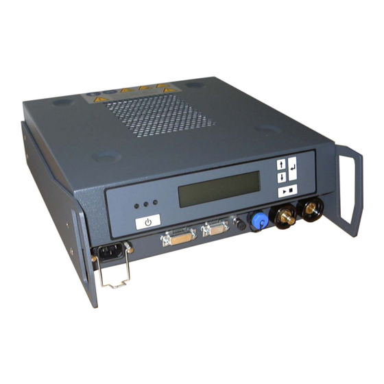
Page 8: Description
MultiCharger 1500 getting damaged. The MultiCharger 1500 is designed as a bench unit, which is cooled by the free flow of air from the base to the top. You should therefore make sure that your MultiCharger 1500 remains uncovered. -
Page 9: Connections
Mains power is connected to the MultiCharger 1500 through a plug for non-heating devices. 3 potential-free relay contacts, which signal various states of the MultiCharger 1500, and also a hardware contact "Remote On/Off", can be connected through a 15-pole SUB-D socket. -
Page 10: 15-Pole Sub-D Socket
1.2.3 USB interface A Mini-USB socket is fitted on the right front side of the MultiCharger 1500, which can be used to connect a laptop or PC. The MultiCharger 1500 can be configured through this interface and software updates can be carried out. -
Page 11: Displays And Operating Controls
1.3.1 Button 1 (On/Off) Button 1 is used to switch the MultiCharger 1500 on and off. If the connected mains power voltage is over 90V, pressing button 1 switches the MultiCharger 1500 on and makes it ready for use. You will also need to use button 1 to re-enable the system if a fault makes the unit shut down. -
Page 12: Led, Green, Yellow, Red
1.3.7 LC Display The MultiCharger 1500’s LCD has two lines and can show 16 characters per line. The current output voltage and current output are displayed on the top line. The bottom line acts as a status display, showing in plain text the operating state and details of any faults that occur (see Appendix A). -
Page 13: Operating Modes
Setting operating mode You can only set the operating mode if the MultiCharger 1500 is ready for use, i.e. if it has been switched on via button 1 (On/Off). However, the unit does not have to be charging a battery and no battery needs to be connected to the charger output. -
Page 14: Output Current In Battery Charging Mode
For example, if the rated current is exceeded for 30 seconds, the MultiCharger 1500 current limit is held at the level of the rated current for 2 minutes 30 seconds. After that time, the rated current can again be exceeded. -
Page 15: External Power Supply (Eps) Mode
Connecting a battery (with a voltage of >1V) to the MultiCharger 1500 before the output voltage is switched on is not allowed. If this is done, a ‘Return voltage’ error message will appear. The output voltage on the MultiCharger 1500 can then not be switched on until the battery is once again removed. -
Page 16: Charging Gel Batteries
MultiCharger 1500 maximum charging current (100A for 12V batteries) being too high for some types of battery. Should this be the case, the MultiCharger 1500 output current limit should therefore be set lower (see section 5.6). For the maximum permitted charging current, refer to the technical specifications of the relevant motorcycle battery. -
Page 17: Internal Monitoring
These are individually described in the following sub-sections. Mains power monitoring If the mains voltage drops below 85V, the MultiCharger 1500 signals a fault and switches off. The message ‘Mains error’ appears on the LCD display. If the mains voltage rises above 90V, the MultiCharger 1500 can be made ready for use by pressing button 1 (On/Off). -
Page 18: Temperature Monitoring
This monitoring function measures the temperature inside the MultiCharger 1500. If this rises above the maximum limit of 90°C, the MultiCharger 1500 signals a fault and is switched off, but not locked. The message ‘Temperature err.’ appears on the LCD display and the red LED comes on. -
Page 19: External Monitoring
Short circuit The MultiCharger 1500 can tell that it has an output short circuit if this occurs in the current limiter and output voltage drops below the set lower limit (default setting 7V or 14V respectively). In this case, the MultiCharger 1500 signals a fault and switches itself off to the locked position. The message ‘Short circuit’... -
Page 20: Reverse Polarity Return Voltage
This monitoring function is only active in EPS mode (see section 2.3). You are not permitted to connect a battery to the MultiCharger 1500 in this operating mode. If you do nevertheless connect a battery before trying to start charging, and connect it the wrong way round, the MultiCharger 1500 signals a fault. -
Page 21: Service Menu
Inappropriate changes can detrimentally impact the way the charger works. None of the settings can be changed unless the MultiCharger 1500 is ready for use, i.e. unless it has been switched on via button 1 (On/Off). However, the unit should not be charging a battery and no battery should to be connected. - Page 22 Service menu structure Service menu: ID code: 0000 Activate Set mode Set voltage Set voltage limit 24V mode Present mode 24V mode off Set 12V Trickle 12V Set Ua max. 12V Ua max. 12V charging trickle voltage Now at: 13.4V Now at: 16.0V Present mode 24V mode on...
- Page 23 Service menu structure Set current limit Set process times Turn on/off autostart Set I-limit CHRG I-limit CHRG 12V Set switch back Switch back time Autostart now Now at: 80A/100A time Now at: 120Min enabled Set I-limit CHRG I-limit CHRG 24V Set maximum Max.
- Page 24 Service menu structure Error log Factory settings Select Language Save entries Software version MC05Dxx Exit menu Display error? Error 9: Load factory Factory settings Sprache aktuell Num. Errors = x xxxxxx settings? loaded Deutsch Error 8…1: Current language xxxxxx English Error 0: Langue active xxxxxx...
-
Page 25: Operating Modes
5.1.1 Charging (CHRG) mode This is a sub-item of the ‘Set mode’ menu and can be used to set the MultiCharger 1500 to battery charging mode. The functioning of this operating mode is described in more detail in section 2.2. -
Page 26: Activate 24V Mode
As soon as the 24V operating modes are deactivated, it is no longer possible to activate these from the ‘Set mode’ menu. If a 24V battery is connected to the MultiCharger 1500 in this state, the unit will display a battery error message. -
Page 27: Set 24V Charging Voltage
5.3.4 Set 24V charging voltage This is a sub-item of the ‘Set voltage’ menu and is used to set the charge voltage for the 24V battery- charging mode. Default setting: 28.8V Setting range: 27.0V – 30.0V 5.3.5 Set 12V EPS voltage This is a sub-item of the ‘Set voltage’... -
Page 28: Set Voltage Limit
Set voltage limit The ‘Set voltage limit’ menu is used to set monitoring limits for overvoltage and undervoltage. 5.4.1 Set Ua max 12V This is a sub-item of the ‘Set voltage limit’ menu and is used to set the monitoring limit for overvoltage where output voltage is 12V. -
Page 29: Output Current Limits
25% for a maximum period of 1 minute. 5.5.1 Set I-limit CHRG 12V This is a sub-item of the ‘Set current limit’ menu and is used to set the MultiCharger 1500 maximum rated current in 12V battery charging mode. Default setting: 80.0A/100 A Setting range: 0.0A –... -
Page 30: Process Times
This time begins as soon as the battery’s charging current drops below 2.5A. After this, the MultiCharger 1500 stays on charge until the expiry of the switch back delay set here. It then switches to trickle charge. -
Page 31: Autostart
This is a sub-item of the ‘Autostart’ menu and is used to enable or disable the autostart function. Enabling autostart means that the MultiCharger 1500 (if switched on and in battery charging mode) will begin the charging process as soon as a battery is connected, with no need for any other instructions to be entered. -
Page 32: Derating
Derating The output power is regulated according to the mains input voltage (see diagram). This prevents the mains input current from exceeding the maximum value. Output power curve: Page 32... -
Page 33: Default Settings
24V operating modes : deactivated The MultiCharger 1500 provides the facility to make permanent changes to the default settings through external software. In this event, the charger’s settings may vary from those shown above. If the default settings are changed, this should be marked in the accompanying documentation. -
Page 34: Technical Data
Technical data Model: 12V/100A - 24V/50A battery charger Nominal output: 1200W Maximum output: 1500W DC output: Rated voltage: 12V/24V Max. output current: 80A at 12V (100A for max. 1 min. in Battery charging mode) 40A at 24V (50A for max. 1 min. in Battery charging mode) Controls: Output voltage static tolerance: 1% Type of control for sudden changes of load: 10% for... - Page 35 Electromagnetic compatibility: Emissions comply with EN 61000-6-3 EN 61000-3-2 EN 61000-3-3 Interference immunity acc. EN 61000-6-2 Protection type: IP 52 Protection class: I as per EN 60335 Operating temperature: -20°C to 60°C, with lower current from 40°C ambient temp. Type of cooling: Natural convection, without fan MTBF: >250,000 hours...
-
Page 36: Appendix A: Status And Error Descriptions
Battery connected wrong way round (section 4.2) Faulty battery Voltage of connected battery not allowed (section 4.3) Clamp contact Connection broken between battery and MultiCharger 1500 (section 4.4) Return voltage Battery connected in EPS mode (section 4.5) EPS reverse pole Battery connected wrong way round in EPS mode (section 4.6)
Need help?
Do you have a question about the MultiCharger 1500 and is the answer not in the manual?
Questions and answers