Advertisement
Quick Links
WELCOME TO THE WORLD OF BARBEQUES GALORE OUTDDOR COOKING
INSTRUCTIONS FOR ASSEMBLY AND USE OF
These instructions contain important information that needs to be followed for the safe assembly and use of your
new barbeque. Please read through carefully and completely prior to assembly.
Take care to remove all packaging materials and protective coatings from the barbeque
IMPORTANT: READ ALL OPERATING INSTRUCTION BEFORE LIGHTING.
By following these instructions for safe and easy operation, you will enjoy years of
satisfying, trouble free outdoor cooking. And when you're fully up and running, you can
visit your retailer for some great accessories and cooking tips to make your experience
even more rewarding. But first things first....
Page 1
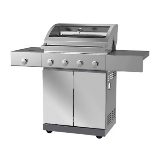
ALFRESCO SERIES BARBEQUES
Code: G4ALF2, G6ALF2
For the safe use and enjoyment of your new barbeque.
For Code: G4ALF2, G6ALF2
before first use.
Tools required:
2 x Adjustable spanners
1 x Phillips head screwdriver
1 x Regular screwdriver
Advertisement

Related Manuals for Barbeques Galore ALFRESCO Series


Summary of Contents for Barbeques Galore ALFRESCO Series
- Page 1 WELCOME TO THE WORLD OF BARBEQUES GALORE OUTDDOR COOKING INSTRUCTIONS FOR ASSEMBLY AND USE OF ALFRESCO SERIES BARBEQUES Code: G4ALF2, G6ALF2 For the safe use and enjoyment of your new barbeque. These instructions contain important information that needs to be followed for the safe assembly and use of your new barbeque.
-
Page 2: Safety Warnings
Safety warnings HAZARDOUS FIRE OR EXPLOSION MAY RESULT IF THESE INSTRUCTIONS ARE IGNORED It is the consumer’s responsibility to see that the barbeque is properly assembled, installed, and taken care of. Failure to follow instructions in this manual could result in bodily injury and/or property damage. FOR YOUR SAFETY IF YOU SMELL GAS: 1. - Page 3 Safety warnings (continued) • Do not perform any servicing on the barbeque yourself. This includes internal adjustment of the regulator and gas valves. Servicing can only be carried out by authorised technicians. • It is important that you install your barbeque exactly as described in these instructions. In particular: you should keep the barbeque clear of combustible material, and you should check for leaks whenever a new connection is made.
- Page 4 Where to put your barbeque This barbeque must only be used in an above ground, open air situation with natural ventilation, without stagnant areas, where gas leakage and products of combustion are rapidly dispersed by wind and natural convection. Any enclosure in which the appliance is used must comply with one of the following: (1) Any enclosure with walls on all sides, but at least one permanent opening at ground level,...
- Page 5 Where to put your barbeque (continued) When used on the ground always place the appliance and cylinder on flat level ground. NEVER light the BARBEQUE with the HOOD in the closed position. NEVER light the SIDE BURNER with the lid in the closed position. Storage of Appliance Storage of this appliance indoors is only permissible if the gas cylinder is disconnected and removed from the appliance.
- Page 6 Contents list. Carefully unpack the carton and check all the parts: 1. One Firebox & 2. One Side 3. One Side 4. One Right Side 5. One Right Hood Assembly Burner Left Burner Shelf Side Shelf Shelf Control Panel Front Panel with Knob Bezel 6.
- Page 7 Contents list (continued) 21. Two Triangle 22. Four Door 23. Two Castors 24. Two Castors 25. One Grease Cup Plates Hinges without Lock with lock 26. One Grease Cup 27. One Grease 28. Two Rubber 29. Five Blue Rings for Knob (Spare for 4B) Foil Liner Cup Bracket Cushions...
-
Page 8: Assembly Instructions
Assembly instructions STEP 1: Attach Castors. WHAT YOU NEED: two x Castors without lock (23) two x Castors with lock (24) A x four x 4 23 x two one x Base panel (6) sixteen x M6*16mm screws (A) D x four x 4 sixteen x M6 flat washer (D) E x four x 4 sixteen x M6 spring washer (E) - Page 9 Assembly instructions (continued) STEP 3: Attach Rear Panel. WHAT YOU NEED: B x five one x Rear panel (9) five x M6*12mm screws (B) Attach the rear panel (9) to the cart with five M6*12mm screws (B). Note: Do not fully tighten the screws until all five screws are started.
- Page 10 Assembly instructions (continued) STEP 5: Attach the Grease Cup Bracket and Cabinet Separator Panel. WHAT YOU NEED: one x Grease cup bracket (27) G x five one x Cabinet Separator Panel (13) two x M6*12mm screws (B) eight x M4*8mm screws (G) B x two a) Attach the grease cup bracket (27) BACK...
- Page 11 Assembly instructions (continued) STEP 7: Fit the Grease Channelling Tray. WHAT YOU NEED: one x Grease channelling tray (14) Slide the grease channelling tray (14) into the grease tray rails. Make sure the drain hole in the grease channelling tray lines up with the drain hole in the separator panel.
- Page 12 Assembly instructions (continued) STEP 9: Adjusting the Door Gap. There are 2 adjustable screws on each door hinge, use them to adjust the door gap if required. Note: It is better to wait until the unit is fully assembled and in position before finally adjusting the doors.
- Page 13 Assembly instructions (continued) STEP 11: Remove the Side Burner. WHAT YOU NEED: one x Side burner assembly (2) Remove the trivet from the side burner assembly (2), then remove the three M4*10mm screws and fibre washers on the side shelf to release the spill tray and burner.
- Page 14 Assembly instructions (continued) STEP 13: Preparation to Attach Side Burner Shelf. WHAT YOU NEED: two x M6*12mm screws (B) Partially screw two M6*12mm screws (B) into the upper holes on the left side panel of the firebox, leave the screw heads protruding approximately five mm out.
- Page 15 Assembly instructions (continued) STEP 15: Attach the Side Burner Valve and Knob. WHAT YOU NEED: one x Knob (12) two x M4*8mm screws (G) a) Insert the side burner valve stem from behind the control panel, through the knob bezel, fix the valve with two M4*8mm G x two screws (G).
- Page 16 Assembly instructions (continued) STEP 16: Attach the side burner. WHAT YOU NEED: one x Spill tray and side burner (kept aside from STEP 11) one x Side burner trivet (kept aside from STEP 11) three x M4*10mm screws (kept aside from STEP 11) three x fibre washers (kept aside from STEP 11)
- Page 17 Assembly instructions (continued) STEP 17: Preparation to Attach Right Side Shelf. WHAT YOU NEED: two x M6*12mm screws (B) Screw two M6*12mm screws (B) into the upper holes on right side panel of firebox, leave the screw heads protruding approximately five mm out.
- Page 18 Assembly instructions (continued) STEP 19: Fit the Grease Cup and Foil Liner. WHAT YOU NEED: one x Grease cup Foil Liner (26) one x Grease cup (25) Put the grease cup foil liner (26) into the grease cup (25), then slide the grease cup into the grease cup bracket.
- Page 19 Assembly instructions (continued) STEP 20: Place the Barbeque Internals. WHAT YOU NEED: two x Flame tamers (17) for 4B two x Flame tamers (17) for 6B one x Cooking grill (19) one x Hot plate (20) one x Warming rack (18) a) Fit the flame tamers (17) onto the support tabs, under the cooking grill.
- Page 20 Configure the alfresco island with separately available units alfresco Configure your island by combining: G4ALF2 G6ALF2 ALISLSINK ALISLRANGE 4 burner bbq 6burner bbq sink unit range unit Note: The barbeques and range units need separate, independent gas supplies. BBQ + Sink unit + Range unit BBQ + Range unit + Sink unit BBQ + Sink unit or Range unit Note: The side burner must only fit onto the LEFT side of the BBQ as above.
- Page 21 Configure the alfresco island with separately available units (continued) How to join your alfresco island units What you need: four M6*16mm screws (A) for each connection (four are included in the bolt packs that come with the sink unit and the range unit) If joining your barbeque to an optional sink unit or to an optional range unit, open the cart door for that optional unit, then connect that unit to your barbeque with four M6*16mm screws (A) as shown.
- Page 22 Checking the gas type and supply Before assembling your barbeque, you should ensure your barbeque is suited to the type of gas which you are going to use. This is a low pressure barbeque and must only be used with propane gas only using the hose and regulator supplied.
- Page 23 Checking for gas leaks and lighting the bbq Always keep the gas cylinder in an upright position. Always close the gas cylinder valve when the barbeque is not in use. Do not subject the cylinder to excessive heat. NEVER STORE YOUR GAS CYLINDER INDOORS. If you store your barbeque indoors, ALWAYS disconnect the cylinder first and store it safely outside.
- Page 24 Checking for gas leaks and lighting the bbq (continued) LIGHTING INSTRUCTIONS After confirming there are no leaks: 1. Open the hood of the barbeque while lighting the main burners. Open the side burner lid while lighting the side burner. 2. Turn all the control knobs clockwise to “OFF” position. 3.
- Page 25 Checking for gas leaks and lighting the bbq (continued) CONTROLLING THE FLAMES The knobs have three basic positions “OFF”, “LOW” & “HIGH”. You can achieve any flame height between “LOW” and “HIGH” by rotating the knob between these two positions. Checking the Flames: Look underneath the barbeque so that you can see the flames.
- Page 26 Also, placing fat absorbent material into the grease cup will avoid splashing and overflowing when the container starts to fill. Suitable fat absorbent material is available from your local Barbeques Galore store. The grease channelling tray and grease cup should be emptied, cleaned and refitted regularly.
-
Page 27: Cooking Hints
Cooking hints It’s easy to keep your food moist and succulent on a barbeque by following these guidelines: • Use tongs instead of a fork when turning meat and poultry. A fork pierces the flesh and causes the juice to seep out. •... - Page 28 NEVER let the hood thermometer temperature exceed 250ºC or the barbeque can dangerously overheat and burn your food. A separate probe thermometer is available as an accessory from all Barbeques Galore stores. This takes the guesswork out of knowing when your food is cooked.
- Page 29 NEVER let the hood thermometer temperature exceed 250ºC or the barbeque can dangerously overheat and burn your food. A separate probe thermometer is available as an accessory from all Barbeques Galore stores. This takes the guesswork out of knowing when your food is cooked.
- Page 30 Internal meat temperatures To obtain correct temperature use an instant-read meat thermometer in the thickest part of the flesh, careful not to touch any bone. Veal Beef Preference Meat Probe temperature Preference Meat Probe Temperature Rare not advised Rare 140ºF / 60ºC Medium 155ºF / 70ºC minimum safe temperature Medium 150ºF / 66ºC Well Done 165ºF / 75ºC...
- Page 31 Cooking times (continued) Page 31...
-
Page 32: Care And Maintenance
Care and maintenance Cleaning your barbeque: Your barbeque will look better and last longer if you keep it clean. Follow these simple steps. The cooking surfaces: While the cooking surfaces are still hot, take a long handled brush and a scraper and remove remaining oil and food scraps. Use an oven mitt to avoid burning yourself. - Page 33 Ensure you replace only with the correct hose and regulator purchased from Barbeques Galore to ensure proper gas connection compatibility. Connect the nut of the hose to the same gas inlet of the barbeque that the old one was connected.
-
Page 34: Troubleshooting Guide
If a service is required for your barbeque, contact your local Barbeques Galore store Phone 1 300 301 392 SERVICING Your gas barbeque should be serviced annually by a competent registered person. - Page 35 Exploded Drawing - Part List for G4ALF2 Page 35...
- Page 36 Exploded Drawing - Part List for G4ALF2 PART NUMBER PART DESCRIPTION QTY PER BBQ QTY PER CODE SPARE PART PACK CP9153117 Hood assembly CP9153110 Hood outer panel CP9153122 Thermometer CP9153081 Glass retainer CP9153113 Rear hood inner panel CP9153112 Rain guard CP9153111 Glass CP9153114...
- Page 37 Exploded Drawing - Part List for G4ALF2 (continued) PART NUMBER PART DESCRIPTION QTY PER BBQ QTY PER SPARE CODE PART PACK CP9153074 Side burner lid hinge CP9153073 Side burner lid CP9153078 Trivet CP9153077 Side burner CP9153072 Side burner Ignition pin CP9153119 Spill tray CP9153076...
- Page 38 Exploded Drawing - Part List for G6ALF2 Page 38...
- Page 39 Exploded Drawing - Part List for G6ALF2 PART NUMBER PART DESCRIPTION QTY PER BBQ QTY PER SPARE CODE PART PACK CP9153149 Hood assembly CP9153144 Hood outer panel CP9153122 Thermometer CP9153081 Glass retainer CP9153147 Rear hood inner panel CP9153146 Rain guard CP9153145 Glass CP9153148...
- Page 40 Exploded Drawing - Part List for G6ALF2 (continued) PART NUMBER PART DESCRIPTION QTY PER QTY PER SPARE CODE PART PACK CP9153073 Side burner lid CP9153078 Trivet CP9153077 Side burner CP9153072 Side burner Ignition pin CP9153119 Spill tray CP9153076 Side burner shelf CP9153130 Side burner front panel CP9153079...
- Page 41 Cart Base Panel as shown below. Serial Number Need More Information? Call your local Barbeques Galore store where barbeque experts will be happy to help you. Phone 1 300 301 392 Or visit us online at: www.barbequesgalore.com.au Barbeques Galore G.L.G. Australia Pty Ltd (ACN 001 185 002).
Need help?
Do you have a question about the ALFRESCO Series and is the answer not in the manual?
Questions and answers