
Related Manuals for Infineon ASCLIN SPI Master 1


Summary of Contents for Infineon ASCLIN SPI Master 1
- Page 1 ASCLIN_SPI_Master_1 SPI master communication via ASCLIN module AURIX™ TC2xx Microcontroller Training V1.0.0 Please read the Important Notice and Warnings at the end of this document...
-
Page 2: Scope Of Work
An ASCLIN module configured as SPI master sends a two bytes message. The two bytes message is sent through MTSR (MOSI) port pin P15.4 in loopback mode. This signal can be visualized on the oscilloscope screen. 2019-10-17 Copyright © Infineon Technologies AG 2019. All rights reserved. - Page 3 › The ASCLIN module in SPI configuration can support master mode only with four-wire or three-wire (without slave select output signal) and up to 16-bit data width. 2019-10-17 Copyright © Infineon Technologies AG 2019. All rights reserved.
-
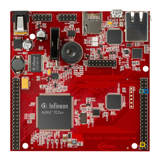
Page 4: Hardware Setup
P15.5 (SPI-MRST) in order to form an internal loopback. Those pins can also be connected to an oscilloscope probe for observing the SPI signal. MRST MTSR Ground 2019-10-17 Copyright © Infineon Technologies AG 2019. All rights reserved. - Page 5 The function IfxAsclin_Spi_initModuleConfig() fills the configuration structure with default values and IfxAsclin_Spi_initModule() initializes the module with the user configuration. All the above functions can be found in the iLLD header IfxAsclin_Spi.h. 2019-10-17 Copyright © Infineon Technologies AG 2019. All rights reserved.
- Page 6 ASCLIN module. › The two bytes message is sent from the g_spiTxBuffer to the g_spiRxBuffer using the function IfxAsclin_Spi_exchange() from the IfxAsclin_Spi.h header file. 2019-10-17 Copyright © Infineon Technologies AG 2019. All rights reserved.
- Page 7 Connect the oscilloscope probe to the MTSR pin (P15.4) › Reset and run the program by pressing the PORST push button › Check the oscilloscope for the SPI signal: Byte 1 Byte 2 2019-10-17 Copyright © Infineon Technologies AG 2019. All rights reserved.
- Page 8 After stepping over this function, the content of the buffers must be equal. Note: The code should run for a few seconds in order to grant enough time for the transmission to be done. 2019-10-17 Copyright © Infineon Technologies AG 2019. All rights reserved.
- Page 9 More code examples can be found on the GIT repository: › https://github.com/Infineon/AURIX_code_examples › For additional trainings, visit our webpage: › https://www.infineon.com/aurix-expert-training › For questions and support, use the AURIX™ Forum: › https://www.infineonforums.com/forums/13-Aurix-Forum 2019-10-17 Copyright © Infineon Technologies AG 2019. All rights reserved.
- Page 10 Infineon Technologies in in personal injury. customer’s applications. The data contained in this document is exclusively intended for technically trained staff.
Need help?
Do you have a question about the ASCLIN SPI Master 1 and is the answer not in the manual?
Questions and answers