Sungrow SG36KTL-M User Manual
Pv grid-connected inverter
Hide thumbs
Also See for SG36KTL-M:
- User manual (103 pages) ,
- Quick installation quide (15 pages) ,
- Quick installation manual (15 pages)

Related Manuals for Sungrow SG36KTL-M


Summary of Contents for Sungrow SG36KTL-M
- Page 1 User Manual SG36KTL-M PV Grid-Connected Inverter SG36KTL-M-UEN-Ver16-201901 Version: 1.6...
-
Page 3: About This Manual
About This Manual This manual is for the inverter SG36KTL-M. The inverter is grid-connected, transformer-less, robust and of high conversion efficiency. The device will bring you profit from PV power system. The manual contains information about the inverter, providing you guidelines to connect the inverter into the PV power system and operate the inverter. - Page 4 Symbols Explanation Important instructions contained in this manual should be followed during installation, operation and maintenance of the inverter. They will be highlighted by the following symbols. DANGER indicates a hazard with a high level of risk which, if not avoided, will result in death or serious injury.
-
Page 5: Table Of Contents
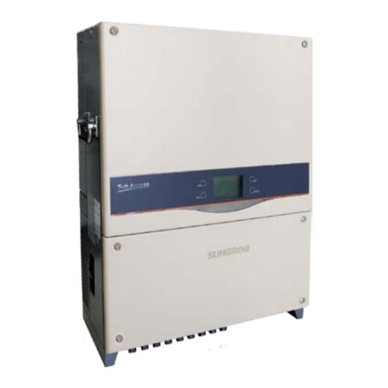
Contents About This Manual ................I Safety Instructions ..............1 Product Introduction ............... 6 Intended Usage ....................6 Product Description ................... 7 2.2.1 Model Description ....................7 2.2.2 Product Appearance ..................... 7 2.2.3 Dimensions of Inverter ..................8 2.2.4 LCD Display Panel ....................8 2.2.5 DC Switch ......................... - Page 6 Electrical Connection ............. 28 Terminals Description ..................28 Connecting Inverter to AC Grid ..............30 6.2.1 AC Side Requirements ..................30 6.2.2 Grid Connection ....................32 Connecting Inverter to PV Arrays ..............36 6.3.1 PV Inputs Configuration ..................36 6.3.2 PV Connection Procedures ................38 Grounding the Inverter ..................
- Page 7 10.2 Inverter Menu Structure ................62 10.3 Main Screen ....................... 63 10.4 Adjust Contrast ....................64 10.5 Checking Running Information ..............64 10.6 Checking History Information ..............66 10.6.1 Checking Fault Records ...................66 10.6.2 Checking History Event Records ..............66 10.6.3 Checking Running Records ................66 10.6.4 Checking Energy Records ................67 10.7 Starting/Stopping ....................
- Page 8 10.11.4 Protection Recovery Setting ............... 85 10.11.5 Protection Parameter Confirmation ............85 10.12 Communication Parameter Setting ............85 10.13 Advanced Parameters Setting..............86 10.13.1 PVS Detect Settings ..................86 10.13.2 10min Max-V ....................87 10.13.3 Grid Unbalance ....................88 11 Appendix ................89 11.1 Technical Data Technical Data ..............
-
Page 9: Safety Instructions
1 Safety Instructions IMPORTANT SAFETY INSTRUCTIONS The SG36KTL-M has been designed and tested strictly according to the international safety regulations. As electrical and electronic equipment, safety instructions related to them must be complied with during installation, commissioning, operation and maintenance. Incorrect operation or work may result in damage to: ... - Page 10 1 Safety Instructions User Manual Always follow the instructions contained in the manual when moving and positioning the inverter. The weight of the equipment can cause injuries, serious wounds, or bruise if improperly handled. During Installation Prior to installing the inverter onto the wall, it is crucial to make certain that the inverter is not electrically connected.
- Page 11 Operate the inverter by strictly following the descriptions in this manual to avoid unnecessary injury to the persons and damage to the device. Arc flash, fire or explosion may follow if otherwise and Sungrow will hold no liability for the damages followed.
- Page 12 1 Safety Instructions User Manual arc flash in the operation area is necessary. If there is arc flash, The operators must receive related safety trainings; Try the best to assess the areas that may appear the electric shock; ...
- Page 13 User Manual 1 Safety Instructions Otherwise it may void any or all warranty rights from Sungrow. There is a risk of inverter damage due to electrostatic discharge! The printed circuit boards contain components sensitive to electrostatic discharge. Wear a grounding wrist band when handling the boards. Avoid unnecessary touch with the boards during replacement.
-
Page 14: Product Introduction
2 Product Introduction 2.1 Intended Usage SG36KTL-M (It will be referred to as inverter hereinafter unless otherwise specified) which is a 3-phase string inverter without transformer, is a crucial unit between the PV strings and utility grid in the PV power system. -
Page 15: Product Description
TN-C TN-C-S Transformer Transformer Transformer SG36KTL-M SG36KTL-M SG36KTL-M If the PV system exceeds the capacity of one inverter, it is possible to connect several inverters into the PV system, with each one connected to an appropriate section of PV inputs and on the AC side they connected in parallel to the grid. -
Page 16: Dimensions Of Inverter
2 Product Introduction User Manual *Image shown here is for reference only. Actual product you receive may differ. Item Name Description Inverter operation data viewing and parameters LCD display panel configuration can be performed via the LCD display panel. They are DC input terminals, AC output terminal Connection terminals and RS485 communication terminal. -
Page 17: Dc Switch
User Manual 2 Product Introduction Fig. 2-4 LCD Display Panel Tab. 2-2 LCD Display Panel Description Name Description “RUN” and “FAULT”. Inverter current state can be known from the indicators two indicators. Detailed definition is shown in Tab. 2-3. Navigate in the LCD menu, set values and so on. Detailed Buttons function is shown in “Tab. -
Page 18: Functions Description
2 Product Introduction User Manual The SG36KTL-M is equipped with MPPTs for 3 DC inputs to ensure that the maximum power can be utilized even in different PV modules installation conditions. Inversion circuit converts DC power into AC power, which will be fed into the utility grid via AC terminals. -
Page 19: Derating
User Manual 2 Product Introduction − Insulation resistance to ground surveillance − Inverter output voltage surveillance − Inverter output frequency surveillance − Residual current protection − DC component of AC output current surveillance − Anti-islanding phenomena protection − Ambient temperature surveillance −... - Page 20 2 Product Introduction User Manual Ambient temperature (℃) Fig. 2-6 Over-temperature Derating (Pf=1) Lower limit of the over-temperature derating: 60% of the nominal power. If the modules temperature and the inner temperature are both exceed the limit, the actual derating power value will be the less one. Grid Under-voltage Derating Once the grid voltage is in the defined range of Vgrid(Vmin…400V), the inverter will decrease the power output.
-
Page 21: Installation Flow
3 Installation Flow Fig. 3-1 shows the installation flow of inverter. Please follow these procedures when installing the inverter. Start Unpacking and Inspection Read User Manual Install Immediately? Storage Mounting Location Selection Moving Inverter Mounting the Inverter Electrical Connection Check before Commissioning Commissioning Troubleshooting Success? - Page 22 3 Installation Flow User Manual Tab. 3-1 Description of Installation Flow Order Description Reference Chapter Unpacking and inspection Section 4.1 Read this manual, especially the section on “safety Chapter 1 instruction” Store the inverter unit if not install immediately Section 4.4 Choose the best installation site Section 5.1 Moving the inverter to installation site...
-
Page 23: Unpacking And Storage
4 Unpacking and Storage 4.1 Unpacking and Inspection The unit is thoroughly tested and strictly inspected before delivery. Damage may still occur during shipping. Check the packing for any visible damage upon receiving. Check the inner contents for damage after unpacking. ... -
Page 24: Identifying Inverter
Fig. 4-2 Nameplate of Inverters *Image shown here is for reference only. Actual product you receive may differ. Item Description SUNGROW logo and product type Technical data of inverter Marks of certification institutions of inverter Company name, website and origin Tab. -
Page 25: Delivery Contents
Eight pairs. Please insert MC4 cable gland to the gland unconnected DC input terminal. 4.4 Storage of Inverter Store the inverter properly when the inverter is not to be installed immediately. Sungrow shall hold no liability for the corrosion of the device or the failure of device... - Page 26 4 Unpacking and Storage User Manual internal components caused by storage of the device not following the requirements specified in this manual. Inverter must be packed into its original carton with the desiccant bags inside. The unit must be packed into original carton and desiccant must be put inside. If the original packaging is not available, an equivalent carton which is able to support the unit weight and size can be used.
-
Page 27: Installing Inverter Onto Wall
5 Installing Inverter onto Wall 5.1 Installation Site Selection Select an optimal installation site for safe operation, long service life and outstanding performance. Take the load capacity of the wall into account. The wall (concrete wall or metal frame) should be strong enough for the weight of the inverter over a long period. ... - Page 28 75°, install the inverter on the frame to meet the requirement for installation angle. The frame and the inverter are installed as shown in the following figure. The rack The final station For detailed frame installation solution, contact Sungrow.
- Page 29 User Manual 5 Installing Inverter onto Wall With an IP65 protection rating, the inverter can be installed both outdoors and indoors. To achieve better running effect The ambient temperature should be within -25℃…60℃. The inverter will operate with power derating if the temperature is too high.
-
Page 30: Moving Inverter To Installation Site
5 Installing Inverter onto Wall User Manual Do not install the inverter in a confined space. The inverter will not work normally if otherwise. Install the inverter where children cannot reach. Do not install the inverter near residential areas. Noise can be produced during inverter operation which may affect the daily life. -
Page 31: Installing The Inverter
User Manual 5 Installing Inverter onto Wall Tool Description Appearance Marker Used to mark the hole positions Measuring Used to measure distances during tape installation Safety gloves To avoid or reduce injury Utility knife Used for unpacking or cutting Wire stripper Used for cable stripping Hydraulic Used to crimp the OT terminal... -
Page 32: Installing On Metal Frame
5 Installing Inverter onto Wall User Manual 27.5 6-11X22 2-4x10 Fig. 5-1 Dimensions of Backplate(unit: mm) The stainless fasteners are supplied for attaching the backplate to metal frame. Fig. 5-2 Dimensions of Fastener Set for Metal Frame(unit: mm) To install the inverter to concrete walls, user needs to purchase expansion bolts with proper size (recommended: M10*65) to fix the backplate to the concrete walls. - Page 33 User Manual 5 Installing Inverter onto Wall Fasten the backplate against the metal frame with bolts and nuts. The Step 5 dimensions of fasteners used in the following diagram are recommended. The torque for fastening the nut is 35 Nm. Install backplate Item Description...
-
Page 34: Installing On Concrete Wall
5 Installing Inverter onto Wall User Manual 5.4.2 Installing on Concrete Wall Step 1 Remove backplate and fasteners from the packaging. Place the backplate onto the chosen concrete wall and adjust it until it is in a Step 2 horizontal position. Mark the positions to drill holes using the backplate as the template. - Page 35 User Manual 5 Installing Inverter onto Wall Install backplate Lift up inverter above the backplate and then slide down to make sure that Step 6 the recesses on the back of the inverter fit perfectly together with the backplate. Step 7 After fit the inverter to the backplate, fasten the inverter to the backplate with two M4×16 screws.
-
Page 36: Electrical Connection
6 Electrical Connection Once the inverter is firmly attached to the appropriate location, it can be connected to the PV power system. Installation shall comply with local regulations and technical rules. Installation shall comply with the relevant instructions of AS 4777.1. All electrical connection should follow the National Wiring Rules of Standard AS/NZS 3000. - Page 37 User Manual 6 Electrical Connection L2 L3 Front view Bottom view Fig. 6-1 Connection Cabinet Description *Image shown here is for reference only. Actual product you receive may differ. Description Description Plinth of DC SPDs (Surge DC switch Protection Devices) Configuration circuit board PV input terminals AC connection terminal block...
-
Page 38: Connecting Inverter To Ac Grid
Scenario 1: Several inverters are operated in parallel connection to the three-phase Low Voltage grid. Inverter n Inverter 1 Inverter 2 Requirements: If the number of the grid-connected inverters exceed 40, please contact Sungrow to confirm the technical solution. - Page 39 Requirements: If the number of the grid-connected inverters exceed 40, please contact Sungrow to confirm the technical solution. The rate voltage on the low-voltage side of transformer must meet the inverter output electrical specification. A neutral point is necessary and must lead outwards as neutral conductor.
-
Page 40: Grid Connection
The maximum nominal AC current of all connected inverters must be taken into account. If the number of the grid-connected inverters exceeds 40, please contact Sungrow to confirm the technical solution. The transformer must be protected from overloading and short circuiting. - Page 41 User Manual 6 Electrical Connection AC combiner box should meet the above requirements. The “3+1” solution shown below is recommended. The max. continuous work voltage of M1, M2, M3 and M4 is 440VAC; The withstanding voltage of the low-voltage winding side of the transformer, the AC cables and the secondary devices (including the relay protection, detection &...
- Page 42 6 Electrical Connection User Manual Withstand ambient temperature; Layout type (inside wall, underground, free air etc.); UV resistance and so on. Connecting Inverter to AC Grid Danger to human life due to high voltage existing inside the inverter! Make sure that all the DC and AC cables to the inverter are not live before you start the electrical work.
- Page 43 User Manual 6 Electrical Connection *Images shown here is for reference only! Actual product you receive may differ. Observe the pin assignment of AC terminal block. If a phase wire is connected to the “PE” terminal, it may permanently destroy the inverter. ...
-
Page 44: Connecting Inverter To Pv Arrays
PV array to the inverter. 6.3.1 PV Inputs Configuration The SG36KTL-M inverter has three PV input areas DC1 input、DC2 input and DC3 input, each with its MPP tracker. There is a risk of inverter damage! The following requirements should be met;... - Page 45 User Manual 6 Electrical Connection PV Input 1 PV Input 2 PV Input 3 To make sure maximum DC power can be utilized, PV strings connected to individual input MPPT should have a homogenous structure, including the same type, the same number, identical tilt and identical orientation. Prior to connecting the inverter to PV inputs, the following electrical specifications must be met simultaneously: Open-circuit...
-
Page 46: Pv Connection Procedures
6.3.2 PV Connection Procedures DC cables from PV strings should be equipped with DC connectors. Sungrow provides corresponding plug connectors in the scope of delivery for quick connection of PV inputs. Pairs of MC4 DC connectors are supplied in the scope of delivery. - Page 47 User Manual 6 Electrical Connection Step 2 Assemble cable ends with crimp Positive Crimp Contact contacts by crimping pliers. Negative Crimp Contact Step 3 Lead cable through cable gland. Positive Insulator Step 4 Insert the crimp contact into the Crimp Contact insulator until it snaps into place.
- Page 48 6 Electrical Connection User Manual 880.0 Check the positive and negative polarity of the PV cells. After confirmation, you can insert the DC connectors into the input terminals on the bottom of the inverter. For the same MPPT, reverse connection of a single string is prohibited. A permanent failure of the system or inverter may follow if otherwise.
-
Page 49: Grounding The Inverter
User Manual 6 Electrical Connection 6.4 Grounding the Inverter Because of the transformer-less design of the inverter, neither the DC positive pole nor the DC negative pole of the PV string is permitted to be grounded. 6.4.1 Grounding System Overview All non-current carrying exposed metal parts of the equipment and other enclosures in the PV power system should be grounded (e.g., PV arrays frame and inverter enclosure). -
Page 50: Second Protective Earth Terminal
6 Electrical Connection User Manual 6.4.2 Second Protective Earth Terminal Position of Second PE Terminals There is a second PE terminal on one side of the inverter and it should be grounded. Fig. 6-3 Second PE terminal The ground connection of this second PE terminal cannot replace the connection of the PE terminal of the AC cables. -
Page 51: Communication Connection
User Manual 6 Electrical Connection 6.5 Communication Connection 6.5.1 Communication Overview The inverter operation information can be transferred via its integrated RS485 interface to a PC with monitoring software (such as Insight), or to data logging device (such as Logger 3000). RS485 is the standard communication choice for inverter. -
Page 52: Communication System
6 Electrical Connection User Manual A converter such as Logger 3000 is needed between inverter and PC. 6.5.2 Communication System For Single Inverter Where there is only one inverter, a RS485 cable enables connection between inverter and data logging device. Inverter RS485 cable Ethernet cable... -
Page 53: Rs485 Communication Connection
User Manual 6 Electrical Connection Inverter 1 Inverter 2 Inverter n RS485 cable RS485-2 RS485-2 RS485-2 Ethernet cable Data Logger 120Ω Ethernet RS485 Ethernet port terminal terminal Shielding layer is grounded Multiple inverters in daisy chain Terminating Resistor Communication connection Inverter n>15 (RS485 bus connection) - Page 54 If there is more than one inverter to communicate with a PC or a data logger, it is crucial to configure the communication parameters of each inverter. See “10.12 Communication Parameters Setting”. Logger 3000 is optional parts and can be ordered from Sungrow.
-
Page 55: Commissioning
Step 3 Suppose there are sufficient sunlight and enough DC power. PV arrays initialize and supply DC power to inverter. The LCD display is activated to check the validity first. If there is a defect on the display, contact Sungrow. - Page 56 7 Commissioning User Manual Press Step 4 to choose country(region) code. Countries Confirm the settings by Pressing ENTER other Step 5 Select the country(region) code according to the inverter’s installation country(region). Each Warning! country(region) code represents Only qualified personnel rare allowed to corresponding local protective parameters adjust following parameters.
- Page 57 User Manual 7 Commissioning If the country(region) code set as DE, Grid codes a Grid codes page as shown in the right will appear, where LV signifying low-voltage grid; signifying medium-voltage grid. Press select grid code and press ENTER confirm.
- Page 58 7 Commissioning User Manual Step 7 After selecting the Grid Code, there Pro-Stage will be a “Pro-stage” type selection screen then corresponding Single-stage sub-menu will come up. For detailed Multi-stage information, please refer “Protective Parameters Setting”. Step 8 Set the inverter time as per local time. Time Incorrect time setting will affect the data logging.
-
Page 59: Disconnecting, Dismantling And Disposing The Inverter
8 Disconnecting, Dismantling and Disposing the Inverter 8.1 Disconnecting the Inverter For maintenance work or any service work, inverter must be switched off. In normal operation, switching off is not necessary. In order to disconnect the inverter from the AC and DC power sources, you should proceed as follows. -
Page 60: Disposing The Inverter
8 Disconnecting, Dismantling and Disposing the Inverter User Manual 8.3 Disposing the Inverter Users should take the responsibility for the disposal of the inverter. Some parts and devices in the inverter, such as the LCD display, batteries, capacitors, may cause environment pollution. Users must comply with the related local regulations to avoid pollution. -
Page 61: Troubleshooting And Maintenance
4. Check whether DC input voltage exceeds the inverter start voltage of inverter. 5. If all above conditions are OK, please contact with Sungrow. 1. A fault is not removed yet. “Fault” indicator 2. Perform troubleshooting in according to fault type in LCD is lit screen. - Page 62 1. Check whether AC circuit breaker is triggered. 2. Check whether AC cables are all firmly connected. Islanding 3. Check whether grid is not in service. 4. If all conditions are OK and this fault still occurs in the LCD screen, contact Sungrow Service Dept..
- Page 63 Grid abnormal solution. detected 3. If the grid frequency is within the permissible range, contact Sungrow Service Dept.. The average grid voltage 1. Wait a moment for inverter recovery. exceeds the permissible 2. If the fault occurs repeatedly, contact...
- Page 64 Sungrow Service Dept.. 1. Wait a moment for inverter recovery. Sampling channel failure 2. If the fault occurs repeatedly, contact Sungrow Service Dept.. If the fault occurs repeatedly, contact Sungrow Current imbalance. Service Dept.. Disconnect and stop the inverter. Wait for ambient ambient temperature to rise above -25 ℃...
- Page 65 It is necessary to replace the SPD. Contact Sungrow Service Dept.. Fault with DC SPD Disconnect the inverter and replace the fuses. Fuse has blown out Contact Sungrow Service Dept.. fault occurred in internal Communication fault of communication of the inverter. However, the inverter continues feeding into the grid.
-
Page 66: Maintenance
Devices Replace the fuse. Every six months check Contact Sungrow to order new DC SPDs. 9.2.2 Maintenance Instruction Fans’ Maintenance There are four fans at the side of the inverter for active cooling during running operation. If the fans are dirty or out of work, the inverter may not be well cooled down and its efficiency may accordingly decrease. - Page 67 User Manual 9 Troubleshooting and Maintenance minutes and then perform maintenance work. Fans’ maintenance work may only be performed by qualified electricians. Step 1 Disconnect the AC circuit breaker. Step 2 Rotate the DC switch to the “OFF” position and then pull off all the PV string inputs Step 3 Wait for at least ten minutes.
- Page 68 A non-conductive fuse indicates a fault in the affected string. Step 6 Check the affected string by installer of the PV generator and replace the defective string fuse with same specification (order from Sungrow). Remove the blown string fuse. Step 7 Step 8 Insert the new fuse into the fuse holder.
-
Page 69: Operation Of Lcd Display
10 Operation of LCD Display 10.1 Description of Button Function Inverter offers two buttons for user to look up the running information and configure parameters. The two buttons have multiple functions. Please refer to Tab. 10-1 before any operation onto inverter. Tab. -
Page 70: Inverter Menu Structure
10 Operation of LCD Display User Manual 10.2 Inverter Menu Structure Fig. 10-1 Menu Tree-English... -
Page 71: Main Screen
User Manual 10 Operation of LCD Display 10.3 Main Screen Once the inverter commissioning is finished, LCD display will enter the main screen as shown in Fig. 10-2. Device address Present P-ac P(%) 33.000 power E-day Today’s energy 15.6 Power curve E-tot 497600... -
Page 72: Adjust Contrast
10 Operation of LCD Display User Manual Current fault P1/1 1 GRID Tab. 10-3 Icon Description Icon Description Inverter is in IAP update process. Inverter in power derating state. Fans inside are working. Inverter is operating in warning state. 10.4 Adjust Contrast Step 1 Press... - Page 73 User Manual 10 Operation of LCD Display Main Screen (Press ENTER)→Menu→Run-inform (Press ENTER) LCD display will show the detailed running information. Scroll pages by pressing /. DC power input: the total PV input power. 00000W DC power input Vdc[V] Idc[A] Pdc[W] Vdc[V]: DC voltage of each input.
-
Page 74: Checking History Information
10 Operation of LCD Display User Manual 10.6 Checking History Information 10.6.1 Checking Fault Records Main Screen (Press ENTER)→Menu (Press )→His-inform (Press ENTER)→Flt-record (Press ENTER) On the “Flt-record” interface, scroll pages forwards Flt-record P 1/2 by pressing, and press to scroll pages ... -
Page 75: Checking Energy Records
User Manual 10 Operation of LCD Display LCD display shows the running records. Press to turn pages and press to view the records of the selected date. 00000W DC power input DC1-1: 4.23A DC2-3: 4.23A Vdc[V] Idc[A] Pdc[W] DC1-2: 4.23A DC3-1: 4.23A 289.4... -
Page 76: Starting/Stopping
10 Operation of LCD Display User Manual Monthly energy histogram: shows the power Monthly energy histogram output every month in a year. Press P1/2 2015 view the monthly energy of the latest 15 years. 10:19000kWh Annual energy histogram: shows the power P1/2 output every year. -
Page 77: System Parameter Setting
User Manual 10 Operation of LCD Display Step 3 A password confirmation screen will occur. Set-param Press to move cursor right and Press input the password 111111. Password: 111111 Press to confirm the password and Step 4 ENTER Set-param enter the “Set-param”... -
Page 78: Time Setting
Please contact Sungrow if there is still time deviation after calibration. 10.9.3 Total Energy Deviation Adjustment If the accumulative value “E-total” in the inverter is different from the value in the external metering device, you should adjust energy by “Energy-adj”... -
Page 79: Load Default
password (Press ENTER) → Sys-param(Press ENTER, Press ×4) → Firmware version(Press ENTER) Inverter shows detailed Firmware version firmware information, including Device Type: SG36KTL-M LCD version and DSP version. firmware version SN: A1405170001 information is read only. Ver: DSP_SG36KTL-M_V11_V1_A_M LCD_SG36KTL-M_V03_A_M 10.10 Running Parameter Setting... - Page 80 10 Operation of LCD Display User Manual Run-param On the “Run-param” screen, press to select one P-Q param Time param ENTER item and press to enter the setting interface. LVRT param For each item, Press to move the cursor and HVRT param Press to set the appropriate value.
-
Page 81: Active/Reactive Power Parameters
User Manual 10 Operation of LCD Display Parameter Description Default Range Set the LVRT to OFF or ON. When it is ON, inverter keep grid-connection for a LVRT param [OFF]/ [ON] certain time when grid fault occurs provide reactive power for grid recovery. -
Page 82: Reactive Power Regulation
10 Operation of LCD Display User Manual P-Q param P-Q Param Q-Var switch [OFF] P-W limits 110.0% +1.000 Rate limit [ON/OFF] Q-Var limits +100.0% Power raise 100%/min Power decline 6000%/min Fault slowup [ON/OFF] Slowup rate 10%/min 10.10.3 Reactive Power Regulation Inverter provides reactive power regulation function. - Page 83 User Manual 10 Operation of LCD Display “Q(P)” Mode[when the country(region) selection is not “IT”] PF changes with the inverter output power. Run-param-Q(P) If the country(region) selection is not “IT” (Italy), Upper PF Cap 1.000 after selecting Q(P) Mode, Press to enter the Lower Power 050.0% Run-param-Q(P) submenu.
- Page 84 10 Operation of LCD Display User Manual “Q(U)” Mode[when the country(region) selection is not “IT”/”TH”] The reactive power ratio changes with the grid Run-param-Q(U) voltage. Lower Q/Sn Ind 050.0% Upper Q/Sn Cap 050.0% If the country(region) selection is not “IT”(Italy) Lower U Limit 095.0% /”TH”(Thailand), after selecting Q(U) mode, Press Upper U Limit 115.0%...
-
Page 85: Reactive Power Setting For Italy/Thailand
User Manual 10 Operation of LCD Display Q/Sn Upper Q/Sn Ind Hysteresis U2 Limit Upper U limit Grid voltage Lower U limit U1 Limit Hysteresis Lower Q/Sn Cap Fig. 10-4 Reactive Power Regulation Curve in Q(U) Mode 10.10.4 Reactive Power Setting for Italy/Thailand If the “Countries”... - Page 86 10 Operation of LCD Display User Manual Parameter Explanation Default Range Step Enter Q(P) regulation mode Uin** when grid voltage is above 105% 100~110% Exit from the Q(P) regulation Uout** mode when grid voltage is 100% 90~100% below Uout *PA < PB≤ PC ** Uin>Uout Defdxlt Cxrve Devidtirn...
-
Page 87: Save P/Q-Set
User Manual 10 Operation of LCD Display Parameter Explanation Default Range Step V1i* Grid voltage at point C (in %) 90~110% V2s* Grid voltage at point A (in %) 108% 90~110% V1s* Grid voltage at point B (in %) 110% 90~110% The max. -
Page 88: Lvrt Parameter
010.00S HVRT tolera volt 130.0% HVRT T2 000.50S This running parameter is optional. You can purchase the device equipped with this optional function. For details, please consult Sungrow. 10.10.9 Derating Parameters ×3)→Set-param(Press ENTER)→ Main Screen (Press ENTER )→Menu (Press ... -
Page 89: Iso Parameters
User can only check the parameter in this interface. The default values of the protection parameters have been preset as per grid code of corresponding countries. To set the protection parameter, please contact Sungrow to acquire advanced password. -
Page 90: Country(Region) Setting
10 Operation of LCD Display User Manual 10.11.1 Country(region) Setting To make the protection parameters setting convenient, inverter provides in-built protection parameters for Countries certain countries. Press to choose countries and press ENTER to confirm. If the country(region) selected is not in the list, please choose Other and then input the protection parameters manually. -
Page 91: Single-Stage Protection Parameter Setting
User Manual 10 Operation of LCD Display ENTER and press to confirm. Grid codes Grid codes Grid codes GR_L GR_IS EN50438 Other Grid codes Grid codes Gird sodes 220V 50Hz RPPs 230V 60Hz If country(region) selected is not the 6 countries Pro-Stage mentioned above, you need not to choose grid code. -
Page 92: Multi-Stage Protection Parameter Setting
10 Operation of LCD Display User Manual 10.11.3 Multi-stage Protection Parameter Setting The following interfaces will appear if Pro-param Multi Pro-param Multi Multi-stage is selected. I-Max-V.grid 000.0V I-Min-V.grid 000.0V Press to select parameter, Press I-Max-V.time 000.00s I-Min-V.time 000.00s to move cursor and Press II-Max-V.grid 000.0V... -
Page 93: Protection Recovery Setting
User Manual 10 Operation of LCD Display 10.11.4 Protection Recovery Setting After setting the protection parameters, inverter Pro-recover enters protection recovery interface. Vmax-recover 000.0V Vmin-recover 000.0V Fmax-recover 00.00Hz Fmin-recover 00.00Hz Tab. 10-12 Description of protection recovery parameters Parameter Explanation Vmax-recover Max. -
Page 94: Advanced Parameters Setting
User can only check the parameter in this interface. The default values of the advanced parameters have been preset as per grid code of corresponding countries. To set the advanced parameters , please contact Sungrow to acquire advanced password. 10.13.1 PVS Detect Settings Main Screen(Press ENTER)→Menu screen(Press ×3)→Set-param (Press ENTER) -
Page 95: 10Min Max-V
User Manual 10 Operation of LCD Display PVS Detect represents the PV strings current abnormal Advanced settings ENTER conditions detection. Press to confirm. PVS Detect 10min Max-v Grid Unbalance Press to select PVS Detect function settings. Press PVS Detect ENTER to confirm the selection. -
Page 96: Grid Unbalance
Rec-value 000.0V This protection function is optional. You can purchase the device equipped with this optional function. For details, please consult Sungrow. 10.13.3 Grid Unbalance Main Screen(Press ENTER)→Menu screen(Press ×3)→Set-param (Press ENTER)→ Enter password (Press ENTER, Press ×4)→Advanced settings(Press ENTER, Press ... -
Page 97: Appendix
11 Appendix 11.1 Technical Data Technical Data Parameters SG36KTL-M Input (DC) Max. PV input voltage 1100 V Min.PV input voltage/Startup input 200 V / 250 V voltage Nominal input voltage 585 V MPP voltage range 200 – 1000 V MPP voltage range for nominal 500 –... -
Page 98: Exclusion Of Liability
11 Appendix User Manual Parameters SG36KTL-M Protection DC reverse connection protection AC short-circuit protection Leakage current protection Grid monitoring DC switch / AC switch Yes / No DC fuse Yes (positive, 15A) PV string current monitoring Overvoltage protection DC Type II / AC Type II... - Page 99 Damages caused by irresistible natural environment The use of supplied software produced by Sungrow Power Supply Co., Ltd. is subject to the following conditions: Sungrow Power Supply Co., Ltd. rejects any liability for direct or indirect damages arising from the use of the SolarInfo software.
-
Page 100: Contact Information
Serial number of the device Fault code/name Brief description of the problem China (HQ) Australia Sungrow Power Supply Co., Ltd Sungrow Australia Group Pty. Ltd. Hefei Sydney +86 551 65327834 +61 2 9922 1522 service@sungrowpower.com service@sungrowpower.com.au Brazil... - Page 101 Tokyo Seoul + 81 3 6262 9917 +82 70 7719 1889 japanservice@jp.sungrowpower.com service@kr.sungrowpower.com Malaysia Philippines Sungrow SEA Sungrow Power Supply Co., Ltd Selangor Darul Ehsan Mandaluyong City +60 19 897 3360 +63 9173022769 service@my.sungrowpower.com service@ph.sungrowpower.com Thailand Spain Sungrow Thailand Co., Ltd.
Need help?
Do you have a question about the SG36KTL-M and is the answer not in the manual?
Questions and answers