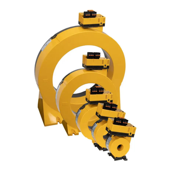
Bender MRCDB300 Series Manual
Ac/dc sensitive residual current monitoring module for mrcd applications
Hide thumbs
Also See for MRCDB300 Series:
- Quick start manual (8 pages) ,
- Quick start manual (8 pages) ,
- Manual (56 pages)

Related Manuals for Bender MRCDB300 Series


Summary of Contents for Bender MRCDB300 Series
- Page 1 Manual MRCDB300 series AC/DC sensitive residual current monitoring module for MRCD applications MANUAL EN MRCDB300-series_D00343_03_M_XXEN/07.2020...
- Page 2 Bender GmbH & Co. KG Postfach 1161 • 35301 Grünberg • Germany Londorfer Str. 65 • 35305 Grünberg • Germany Tel.: +49 6401 807-0 • Fax: +49 6401 807-259 E-Mail: info@bender.de • www.bender.de © Bender GmbH & Co. KG Alle Rechte vorbehalten.
-
Page 3: Table Of Contents
Table of Contents 1. General instructions ................7 How to use this manual .................. 7 Technical support: service and support ............ 7 Training courses ....................8 Delivery conditions ................... 9 Inspection, transport and storage ............... 9 Warranty and liability ..................9 Disposal ....................... - Page 4 Table of Contents Connection RS-485 interface (Modbus RTU) ......... 25 Installation instructions for measuring current transformers ..25 4.7.1 Protective conductors and live conductors ........... 26 4.7.2 Bending cables ....................26 4.7.3 Routing cables centrally ................26 5. Commissioning ..................27 Setting addresses ....................
- Page 5 Table of Contents 8. System states: LED and output relays ..........51 9. Frequency responses ................53 Low passes LP ....................53 Type B+ ....................... 53 Type B ........................54 Fire protection 100 kHz ................. 54 10. Technical data ..................55 10.1 Tabular data .......................
-
Page 7: General Instructions
1.2 Technical support: service and support For commissioning and troubleshooting Bender offers: First level support Technical support by phone or e-mail for all Bender products • Questions about specific customer applications • Commissioning • Troubleshooting... -
Page 8: Training Courses
**Mo-Thu 7.00 a.m. - 4.00 p.m., Fr 7.00 a.m. - 1.00 p.m 1.3 Training courses Bender is happy to provide training regarding the use of test equipment. The dates of training courses and workshops can be found on the Internet at www.bender.de ->... -
Page 9: Delivery Conditions
ZVEI (Zentralverband Elektrotechnik- und Elektronikindustrie e.V., (German Elec- trical and Electronic Manufacturers' Association) also applies. Conditions of sale and delivery can be obtained from Bender in printed or electronic for- mat. 1.5 Inspection, transport and storage Inspect the dispatch and equipment packaging for damage, and compare the contents of the package with the delivery documents. -
Page 10: Disposal
13 August 2005 must be taken back by the manufacturer and disposed of properly. For more information on the disposal of Bender devices, refer to our website at www.bender.de -> Service & support. -
Page 11: Safety Instructions
2. Safety instructions 2.1 General safety instructions Part of the device documentation in addition to this manual is the enclosed " Safety in- structions for Bender products". 2.2 Work activities on electrical installations Only qualified personnel working in electrical engineering and electronics are permitted to carry out the work necessary to install, commission and run a device or system. -
Page 12: Device Description
3. Device description 3.1 Area of application The AC/DC sensitive device series MRCDB30… is used in combination with a CTBC… as additional protection (protection against indirect contact) in earthed systems (TN and TT systems) in which AC or DC fault currents may occur. Part of these systems are particularly loads containing six-pulse rectifiers or one-way rectifiers with smoothing, such as converters, battery chargers, construction site equip- ment with frequency-controlled drives. -
Page 13: Variants
Device description • AC/DC sensitive type B+ measured value acquisition acc. to VDE 0664-400 (depend- ing on variant) • Exchangeable electronic enclosure without mechanical separation of the primary conductors • Extension/retrofitting or modification of functionalities in case of changed monitor- ing requirements •... -
Page 14: Functional Description
Device description 3.4 Functional description Residual current I Δn The residual current monitoring module measures both AC and DC currents. Tripping takes place based on the determined r.m.s. value. When the response value set for I Δn2 (alarm) is exceeded by a residual current, the output relay K2 switches an undervoltage release (recommended) or a shunt release (N/O operation) within the required tripping time and the LED lights up red. - Page 15 Device description 3.4.1 Delay times , and t The times t , t, t and t described below delay the output of alarms via LEDs, relays and Modbus RTU. Recovery time The recovery time is the time the device needs to be ready for measurement after con- necting the supply voltage U Start-up delay After connecting the supply voltage U...
-
Page 16: Installation And Connection
4. Installation and connection Only qualified personnel working in electrical engineering and electronics are permitted to carry out the work necessary to install, commission and run a device or system. Risk of electrocution due to electric shock! Touching live parts of the system carries the risk of: •... -
Page 17: Installing The Device
Installation and connection 4.2 Installing the device 4.2.1 Dimension diagrams CTBC20(P)/CTBC35(P) CTBC60(P) CTBC120(P)/CTBC210(P) MRCDB30… Fig. 4.1: Dimension diagrams CTBC… and MRCDB30… Type ø 20 MRCDB3…-CTBC20(P) ø 35 MRCDB3…-CTBC35(P) ø 60 MRCDB3…-CTBC60(P) ø 120 MRCDB3…-CTBC120(P) ø 210 MRCDB3…-CTBC210(P) MRCDB30x All dimensions in mm, tolerance ±0.5 mm MRCDB300-series_D00343_03_M_XXEN/07.2020... -
Page 18: Mountings
Installation and connection 4.2.2 Mountings CTBC20(P)/CTBC35(P) CTBC60(P) CTBC120(P)/CTBC210(P) Type CTBC20(P) 31.4 2 x ø 5.5 CTBC35(P) 49.8 2 x ø 5.5 CTBC60(P) 2 x ø 6.5 CTBC120 4 x ø 6.5 CTBC210 4 x ø 5.5 all dimensions in mm, tolerance ±0.5 mm 4.3 Assembly Fig. -
Page 19: Connecting The Device
Installation and connection 4.4 Connecting the device Risk of electrocution due to electric shock! Touching live parts of the system carries the risk of: • An electric shock DANGER • Damage to the electrical installation • Destruction of the device Before installing and connecting the device, make sure that the installation has been de-energised. -
Page 20: Wiring Diagrams
Installation and connection 4.5 Wiring diagrams The following applies to all wiring diagrams: • The use of a type 2 surge protection device (SPD) is mandatory due to possible impulse voltages and in order to comply with normative requirements. • The surge protection device must be connected upstream of the power supply unit on the supply side. -
Page 21: N/C Principle With Contact Feedback
Installation and connection 4.5.2 N/C principle with contact feedback F 6 A DC 24 V 24 V MRCDB30...-CTBC... 22 24 U< 22 24 12 14 Alarm Prewarning * surge protection device Fig. 4.4: Wiring diagram MRCDB30…(N/C principle with contact feedback) The contact feedback ensures that the trip circuit is in the desired switching state. -
Page 22: N/O Principle Without Contact Feedback
Installation and connection 4.5.3 N/O principle without contact feedback F 6 A DC 24 V 24 V MRCDB30...-CTBC... 22 24 22 24 12 14 Alarm Prewarning * surge protection device Fig. 4.5: Wiring diagram MRCDB30…(N/O principle without contact feedback) MRCDB300-series_D00343_03_M_XXEN/07.2020... -
Page 23: N/O Principle With Contact Feedback
Installation and connection 4.5.4 N/O principle with contact feedback F 6 A DC 24 V 24 V MRCDB30...-CTBC... 22 24 22 24 12 14 Alarm Prewarning * surge protection device Fig. 4.6: Wiring diagram MRCDB30…(N/O principle with contact feedback) We recommend operating the alarm relay K1 according to the N/C principle. -
Page 24: Connection Rs-485 Interface (Modbus Rtu)
Installation and connection 4.6 Connection RS-485 interface (Modbus RTU) MRCDB30… COM465IP first device last device 120 Ω 120 Ω DIP switch wire jumper Fig. 4.7: Connection RS-485 interface The internal 120 Ω terminating resistor can be connected by using the wire jumper. The internal 120 Ω... -
Page 25: Installation Instructions For Measuring Current Transformers
Installation and connection 4.7 Installation instructions for measuring current transformers Application in railway vehicles/DIN EN 45545-2:2016! If the horizontal or vertical distance to adjacent components which do not meet the requirements in table 2 of DIN EN 45545-2 is less than 20 mm or less than 200 mm respectively, they are to be regarded as grouped. -
Page 26: Protective Conductors And Live Conductors
4.7.1 Protective conductors and live conductors Make sure that all current-carrying cables are rout- ed through the measuring current transformer. Never route an existing protective conductor through the measuring current transformer. The cable diameter should not exceed half the cur- rent transformer diameter. -
Page 27: Commissioning
Commissioning 5. Commissioning 5.1 Setting addresses Every MRCDB3… has a factory-set Modbus address. The address is 1XX, where XX = the last two digits of the serial number. Example: Serial number = 12345678 --> Modbus address = 178 If the preset address is to be changed, this can be done •... - Page 28 Commissioning Address modification procedure Phase Action Flashes red (A, error: no measuring Supply the electronic module with power current transformer) Flashes red (A, error) Flashes red quickly Press and hold "T" until the LED flashes red very quickly; release afterwards (B, mode change) Flashes red quickly (C, ready for address setting mode)
-
Page 29: Offset Calibration
Commissioning 5.2 Offset calibration The residual current monitoring module must be calibrated to the system to be moni- tored so that the selected protective function can be fulfilled. Each electronic module MRCDB30… must be individually calibrated to the CTBC… built-in measuring current transformer. -
Page 30: Completing And Checking Installation
Procedure of the first offset calibration Phase Action Install the measuring current transformer in the system Plug the electronic module and the measuring current transformer together (see Chapter 4.5) Disconnect the electronic module from the supply voltage Press and hold the "T" button lights red permanently (not ready for operation) Press and hold the "T"... -
Page 31: Test, Reset, Function Test
Test, reset, function test 6. Test, reset, function test 6.1 Periodic self test The MRCDB… electronic module carries out a self diagnosis at regular intervals and thus ensures the device function. The electronic module feeds a test current into the test winding of the measuring current transformer. - Page 32 the test intervals mentioned in DGUV V3 (German Social Accident Insurance Regulation 3) are adhered to. The test intervals are to be interpreted in accordance with the risk as- sessment. The recurrent tests must include at least the following: • Testing the environmental conditions for pollution, mechanical damage or insula- tion damage.
-
Page 33: Modbus Register
Modbus register 7. Modbus register This chapter provides a complete description of the Modbus register for the MRCDB300/RCMB300 series to allow access to information. The following Modbus function codes are supported: • Holding register for reading out values (Read Holding Register; function code 0x03) •... -
Page 34: Register Areas
Modbus register 7.1.3 Register areas Area Start address End address Info 3999 Detailed measured values 4000 7999 Simple measured values 8000 11999 History 12000 15999 Parameters 16000 19999 Control commands 20000 23999 Reserved 24000 27999 Reserved 60000 60099 7.1.4 Representation of values Value Description Value... -
Page 35: Alarm Assignments
Modbus register 7.1.5 Alarm assignments Bit number Description Start alarm (relay 1) Device error (relay 1) Manual self test (relay 1) AC residual current (relay 1) DC residual current (relay 1) RMS residual current (relay 1) 6…15 Reserved Start alarm (relay 2) Device error (relay 2) Manual self test (relay 2) AC residual current (relay 2) - Page 36 Modbus register Property Register Format Description Value/unit/comment Factory settings Maximum 96 characters String UTF- Bender GmbH & 1098 Manufacturer name (\0 = end character) Co. KG\0 Character is in the LoByte Application 1194 UINT16 (MRCDB3…) D number 610(RCMB3…) Application Version number multiplied by 100. Example: 123...
-
Page 37: Detailed Measured Values
Modbus register 7.3 Detailed measured values Register Property Format Description Value/unit 4000 UINT16 Measuring channel number (1) 4001 Float32 Residual current measured value (AC) 4003 UINT16 Test and alarm status 4004 UINT16 Range and unit 4005 UINT16 Description 4006…4015 Reserved 4016 UINT16 Measuring channel number (2) -
Page 38: General Measured Values
Modbus register 7.4 General measured values Unit Register Property Format Description Value Comment Measured value (AC) 8000 Float32 Δn Measured value (DC) 8002 Float32 Δn Measured value (RMS) 8004 Float32 Δn 8006 Float32 Device/info code Device error and status information 8008 UINT32 Number of alarms... -
Page 39: Error Codes
The error is deleted either by switching the device off/ on or by performing a reset. The device restarts com- pletely (switching of relays possible). If the error per- sists, return the device or contact Bender service. 6.10 No initial off- No offset measurement has Perform offset measurement. - Page 40 Action code group 9.03 μC system error Switch the device off and on again. If error persists, return the device or contact Bender service. 9.60 Parameter Parameter outside permissible Switch the device off and on again. Reset device to fac-...
-
Page 41: History
Modbus register 7.5 History A maximum of 50 events can be stored. The events are sorted chronologically in such a way that the most recent event is number 1 and the oldest event is number 50. The history memory is buffered and is only updated by reading register 12000 so that the sequence does not change during readout (due to a new history event). -
Page 42: Device Parameters And Factory Settings
Modbus register 7.6 Device parameters and factory settings = response delay = delay on release Factory settings Value range Description Unit MRCDB {Step size} Limit value 0.03…3.00 A 16000 0.03 A 0.3 A 0.03 A 0.3 A 0.03 A alarm {1 mA} Limit value 50 …... - Page 43 Modbus register Factory settings Value range Description Unit MRCDB {Step size} 1 = N/C principle 16038 Relay mode 2 = N/O principle Alarm assignment 16039 start alarm Alarm assignment 16040 device error Alarm assignment 16041 2 (fixed) test Alarm assignment limit value violation 16042 Alarm assignment...
- Page 44 Modbus register Factory settings Value range Description Unit MRCDB {Step size} 1 = N/C principle 16056 Relay mode 2 = N/O principle Alarm assignment 16057 2 (fixed) 2 (fixed) start alarm Alarm assignment 16058 2 (fixed) 2 (fixed) device error Alarm assignment 16059 2 (fixed)
- Page 45 Modbus register Factory settings Value range Description Unit MRCDB {Step size} 16078 Modbus address 1…247 Last 2 digits of the serial number + 100 1200 2400 4800 16079 Baud rate 9600 19200 19200 38400 57600 1 = 8N2 2 = 8O1 3 = 8E1 16081 Parity/stop bit...
- Page 46 Modbus register Adjustable for Register Meaning MRCDB MRCDB MRCDB MRCDB MRCDB entry Low pass 60 Hz — — — Low pass 500 Hz — — — Low pass 1 kHz — Low pass 2 kHz — Low pass 5 kHz —...
-
Page 47: Control Commands
Modbus register 7.7 Control commands Comment Factory Register Property Format Description Unit setting Value Manual device tripping test. Same behaviour as test button. Read 20000 UINT16 Device test 1 = test inactive/completed 2 = test running Write 2 = start test Deleting fault and alarm messages. -
Page 48: Additional Function Codes
Modbus register Comment Factory Register Property Format Description Unit setting Value 0 = no test alarm 1 = test alarm channel 1 20010 UINT16 2 = test alarm channel 2 Test alarm 3 = test alarm channel 3 4 = test alarm channel 4 20011…23999 Reserved Tab. -
Page 49: Get Com Event Counter (Function Code 0X0B)
7.8.2 Get Com Event Counter (function code 0x0B) Response Notes If a previously received command is still being processed, then the answer is 0xFFFF. Otherwise it is 0x0000. (Current Status implementation: always 0x0000). Event Count It is a 16-bit counter. This means that a maximum of 65535 is counted. There is no overflow. Tab. - Page 50 MRCDB300-series_D00343_03_M_XXEN/07.2020...
-
Page 51: System States: Led And Output Relays
System states: LED and output relays 8. System states: LED and output relays The LED indicates the system state by means of colours and lighting/flashing. The changeover contacts of relay outputs K1 and K2 have defined switching positions for each system state. GREEN Changeover Changeover... -
Page 52: Frequency Responses
9. Frequency responses 9.1 Low passes LP ∆n 10 x I ∆n 5 x I ∆n 1 x I ∆n 1000 10000 100000 f (Hz) 9.2 Type B+ 1000 (mA) ∆n = 300 mA ∆n = 100 mA ∆n = 30 mA ∆n 1000 10000... -
Page 53: Type B
Frequency responses 9.3 Type B 1000 ∆n (mA) = 30 mA ∆n 1000 f (Hz) 9.4 Fire protection 100 kHz 1000 (mA) ∆n = 300 mA ∆n = 100 mA ∆n = 30 mA ∆n 1000 10000 100000 f (Hz) MRCDB300-series_D00343_03_M_XXEN/07.2020... -
Page 54: Technical Data
Technical data 10. Technical data (…)* = factory setting 10.1 Tabular data Insulation coordination acc. to IEC 60664-1/IEC 60664-3 Definitions Measuring circuit (IC1) .......Primary conductors routed through the current transformer Secondary (IC2) .........Terminal block 1 (24 V, GND, D1, DG, T/R, GND, A, B, X1, X2) Control circuit 1 (IC3) ................Terminal block 2 (11,12,14) Control circuit 2 (IC4) ................Terminal block 3 (21,22,24) Rated insulation voltage...................... - Page 55 Technical data Measuring circuit Internal diameter measuring current transformer ......see dimension diagrams page 17 Characteristics according to IEC 62020 and IEC/TR 60755 ......... AC/DC sensitive, type B Response value I ............... see frequency responses from page 52 Δn MRCDB301 (protection of persons) ..................30 mA MRCDB302 (fire protection)....................
- Page 56 Technical data Delay on release t .......................2 s after reset MRCDB300-series_D00343_03_M_XXEN/07.2020...
- Page 57 Technical data Operating time t at 1 x I ..........................≤ 180 ms Δn at 2 x I ..........................≤ 130 ms Δn at 5 x I ..........................≤ 20 ms Δn Response time t Recovery time t ..........................≤ 1 s Indication Multicolour LED ......red/green, Refer to "System states: LED and output relays"...
- Page 58 Technical data Classification of mechanical conditions acc. to IEC 60721 Stationary use (IEC 60721-3-3) ....................3M11 Transport (IEC 60721-3-2)......................2M4 Long-term storage (IEC 60721-3-1) ..................1M12 Connection Required terminals are included in the scope of delivery (except MRCDB304). Terminal block 1 Manufacturer ......................
-
Page 59: Standards And Certifications
Technical data Other Operating mode .......................continuous operation Mounting ..........................any position Degree of protection, internal components (DIN EN 60529) ..............IP40 Degree of protection, terminals (DIN EN 60529).................IP20 Flammability class ........................UL94 V-0 Software............................D0579 Weight MRCDB30… .......................... ≤ 100 g CTBC20 ........................... -
Page 60: Measuring Current Transformers
Technical data 10.3.2 Measuring current transformers Type Description Art. No. CTBC20 Measuring current transformer, internal diameter 20 mm B98120001 CTBC20P Measuring current transformer shielded, internal diameter 20 mm B98120002 CTBC35 Measuring current transformer, internal diameter 35 mm B98120003 CTBC35P Measuring current transformer shielded, inside diameter 35 mm B98120004 CTBC60 Measuring current transformer, inside diameter 60 mm... -
Page 61: Index
INDEX N/C principle 21 N/C principle (with contact feedback) 22 N/O principle 23 Address setting 27 Application example 15 Area of application 13 Output relays 51 Assembly 19 Periodic self test 31 Bending cables 26 Protective conductors and live conductors 26 DC calibration 29 Route-through direction 26 Device features 13... - Page 62 MRCDB300-series_D00343_03_M_XXEN/07.2020...
- Page 64 All rights reserved. Reprinting and duplicating only with permission of the publisher. Bender GmbH & Co. KG P.O. Box 1161 • 35301 Grünberg • Germany Londorfer Str. 65 • 35305 Grünberg • Germany Tel.: +49 6401 807-0 • Fax: +49 6401 807-259 E-Mail: info@bender.de •...
Need help?
Do you have a question about the MRCDB300 Series and is the answer not in the manual?
Questions and answers