Advertisement
Quick Links
Advertisement

Related Manuals for TOORX BRX90


Summary of Contents for TOORX BRX90
- Page 1 INSTRUCTION...
- Page 2 All data displayed are approximate guidance and cannot be used in any medical application.
-
Page 3: Assembly Instructions
ASSEMBLY INSTRUCTIONS Step 1 Assembly the rear and front stabilizer (N&M) with 4 bolts (M-1). Step 2 Assemble the left hand pedal (K-L) and the right hand pedal (K-R) to the crank. Step 3 Pass through the handlebar post (C) from the plastic cover (I-1). - Page 4 ASSEMBLY INSTRUCTIONS Step 4 Attach the handlebar (B) to the handlebar post between the steel covers, secure the steel cover assembly using one flat washer (C-1), one spring washer (C-2), one bushing (C-3) and one knob (C-4). Step 5 Plug in the cables (A-1&B-2) between the computer and the handlebar post, plug in the motor cable (A-2&C-5) between computer and handle bar post.
- Page 5 ASSEMBLY INSTRUCTIONS Step 6 Insert the seat post (D) into the main frame through the plastic sleeve. Select the ideal hole position on the seat post. Insert the knob (E-6) into the hole. Tighten fully the knob. Step 7 Connect the saddle (D-6) and the slider (D- 5) s.
- Page 6 Step 8 Put the handle bar plastic cover left & right (C-11&C-6) onto the handle bar, secure it with screws (C-8&C-9) as left drawing. Step 9 Assemble the slider cover left & right (D- 8&D-7) onto the slider set, fix it with screws (C-8&D-9).
-
Page 7: Parts List
PARTS LIST Item Description Q’ty Item Description Q’ty Computer C-circle Pulse cable (upper) Idle Motor cable Nylon nut M8 Screw M5*10 Bushing Φ10*Φ14*6L Handle bar Idle wheel Screw M4*20 Flat washer Pulse cable (lower) Screw M8*20L End cap Spring Foam grip Flywheel Hand pulse Screw 3/8″-26... - Page 8 Seat post knob M16 Spring washer Screw Flat washer Semicircle washer Front stabilizer Motor Front end cap (left) Plastic pulley Front end cap (right) Bushing Φ17*5T Screw M8*60L Rear stabilizer Axle assembly Screw M8*10L Rear end cap (left) Belt Rear end cap(right) Wave washer Inner hex.
-
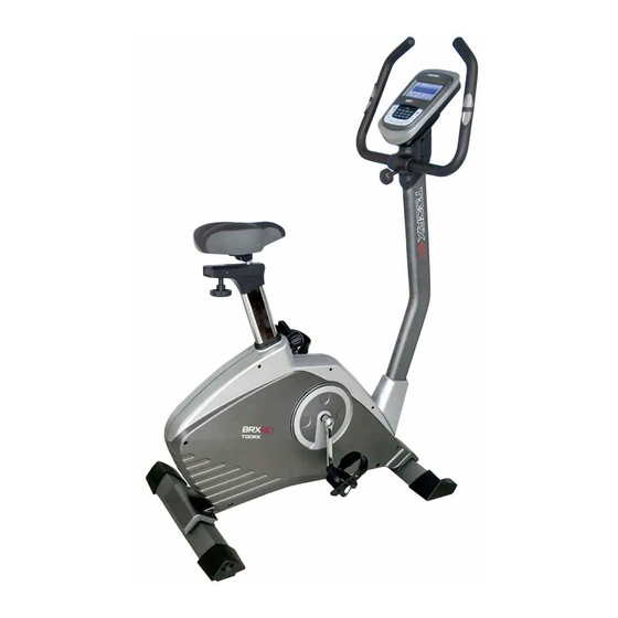
Page 9: Complete Bike Assembly
COMPLETE BIKE ASSEMBLY... -
Page 10: Computer Operation
Computer Operation I. To operate the monitor A-0. Plug in the AC Adapter to power supply. You will see this first screen followed by the next one. A-1. You may select different training mode of MANUAL, PROGRAM, USER or TARGET H.R. by pressing UP, DOWN buttons (a1). Press MODE button to confirm. - Page 11 Computer Operation B-6 During all training period, you may press ST/STOP to stop monitor counting at anytime. C. Training in PROGRAM mode - press UP button until PROGRAM shows up on the upper line, press MODE to confirm. (c1) (c2) (c3) (c4) C-1 The initial set program profile is P1 (c1 &...
- Page 12 Computer Operation left-upper corner) and beep for 8 times to remind you.(d6) D-5 You may press ST/STOP button to start training again. The function which has achieved to zero will start from previous set data counting down, and other set function data will keep counting up or down from previous records. D-6 During all training period, you may press ST/STOP to stop monitor counting at anytime.
- Page 13 Computer Operation Displays current training rotations per minute. TIME Count up - If NO preset target, Time will count up from 00:00 to maximum 99:59 with each increment of 1 second. Count down - If training with preset Time, Time will count down from preset value to 00:00.Each preset increment or decrement of 1 minute between 1:00 to 99:00.
- Page 14 GARLANDO SPA Via Regione Piemonte, 32 - Zona Industriale D1 15068 - Pozzolo Formigaro (AL) - Italy www.toorx.it - info@toorx.it...
Need help?
Do you have a question about the BRX90 and is the answer not in the manual?
Questions and answers