Table of Contents
Advertisement
Quick Links
Advertisement
Table of Contents

Related Manuals for TOORX BRX Compact MultiFit


Summary of Contents for TOORX BRX Compact MultiFit
- Page 1 INSTRUCTION...
-
Page 2: Product Overview
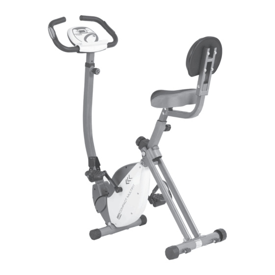
PRODUCT OVERVIEW Pulse Sensor Handlebar Meter Adjustment Knob Upright Back Cushion Adjustment Knob Back Frame Top Cover Back Support Left Pedal Seat Left Front Cover Left Chain Cover End Cap End Cap Front Transport Wheel Stabilize Rear Stabilizer THEFOLLOWINGTOOLS ARE INCLUDED Wrench: FOR ASSEMBLY Allen Wrench (5mm) w/ Screwdriver:... -
Page 3: Hardware Identification Chart
HARDWARE IDENTIFICATION CHART Figure Description Carriage Bolt (M8*1.25*60mm) Carriage Bolt (M8*1.2548 mm) Bolt, Button Head (M8* 40 mm) Screw, Round Head (M6 x 1 x 12mm) Acorn Nut (M8) Arc Washer (M8) Washer (M8) Nut M8 Adjustment Knob Pull Pin... - Page 4 Place all parts from the box in a cleared area and position them on the floor in front of you. Remove all packing materials from your area and place them back into the box. Do not dispose of the packing materials until assembly is completed. Read each step carefully before beginning.
-
Page 5: Assembly Instruction
STEP 4: Attach the Seat (B24) to the Seat Post (A6) with Nylock Nuts (M8) (D25) and Washer (M8) (D38). Insert the Seat Post (A6) into the Main Frame (A1) and secure with the Adjustment Knob (D1). NOTE: 1. Make sure that the pin on the Adjustment Knob (D1) is inserted into one of the holes in Seat Post (A6). - Page 6 STEP 7: Insert the onto the Upright (A3) and tight it by using Adjustment Knob Handlebar (A15) (D1). Attach the Handlebar (A15) to the Upright (A3) by using the Bolt, Button Head M8*40 (D7). STEP 8: Connecting Meter Transmission Wire (C2) into the Sensor Bracket (C13)
- Page 7 STEP9: Tighten the Left Strap (B29) and Right Strap (B30) to the Left Pedal (B27) and Right Pedal Lock and tight the Left Pedal (B27) and Right Pedal (B28) on the Left Crank (C5) (B28). and Right Crank (C6) by using the Wrench. FUNCTION INSPECTION: Visually inspect the Bike to verify that assembly is as shown in the above illustration.
- Page 8 OPERATIONAL INSTRUCITONS USING THE FITNESS METER POWER ON: Pedal movement or press the button. POWER OFF: Automatically shuts off after four minutes of inactivity. MODE BUTTON: Press to select display functions, including SCAN, TIME, SPEED, DISTANCE, CALORIES, ODOMETER, and PULSE. Press and hold for two seconds to reset all functions to zero, except ODOMETER.
- Page 9 HOW TO INSTALL AND REPLACE BATTERIES Open the Battery Door on the back of the meter. The meter operates with two AAA batteries, the batteries are not included. Refer to the illustration to install or replace the batteries. NOTE: 1. Do not mix a new battery with an old battery. 2.
-
Page 10: Load Adjustment
LOAD ADJUSTMENT To increase the load, turn the Adjustment Knob (B32) clockwise. To decrease the load, turn the Adjustment Knob (B32) counterclockwise. There are eight levels for the load adjustment. SEAT ADJUSTMENT Proper seat adjustment is important. Turn the Adjustment Knob (D1) to loosen, then pull the Adjustment Knob (D1) to release the pin. - Page 11 OPERATIONALINSTRUCTIONS STORAGE • To store the BIKE, simply keep it in a clean dry place. • To avoid damage to the electronics, remove the batteries before storing the BIKE for one year or more. • To move the BIKE, hold the HANDLEBAR and tilt the BIKE onto the Wheels of the Stabilizer at the front. •...
- Page 12 OPERATIONALINSTRUCTIONS repair is made. Keep your BIKE clean by wiping it off with an absorbent cloth after use. UPRIGHT ADJUSTMENT Refer to the illustrations below. The angle of the M e t e r ( C 1 ) can be set to different angles from Position 1 to Position 5.
- Page 13 TOCONTACTCUSTOMERSERVICE...
-
Page 14: Parts List
PARTS LIST TOCONTACTCUSTOMERSERVICE A. Welding Parts Description Main Frame Rear Frame Front Stabilizer Seat Support Back Frame Back Support Rear Stabilizer Lever Magnetic Bracket Shaft Handlebar B. Plastic Parts Description Left Chain Cover Right Chain Cover Top Cover Left Front Cover Right Front Cover Lever cover Hollow Cap... - Page 15 Foam Grip 400 Left Pedal TOCONTACTCUSTOMERSERVICE Right Pedal Left strap Right strap Crank Cap Adjustment Knob Adjustment Knob Bracket Plastic WasherΦ10.2*Φ14 Stopper Endcap Bearing Housing Hand grip Plug C. Electrical parts Description Meter Connection Wire Folding Axis Left Crank Right Crank Flywheel V-Ribbed Belt (230J) V-Ribbed Belt(240J)
- Page 16 D. Hardware TOCONTACTCUSTOMERSERVICE Description Adjustment Knob Ball Pin Allen Wrench Carriage Bolt M8*60 Hex Head Bolt M6*45 Bolt, Button Head M8*40 Carriage Bolt M8*48 Bolt, Button Head M8*75 Bolt, Button Head M8*20 Eye Bolt M6 Hex Head Bolt M8X55 Hex Head Round Bolt M8X68 Screw, Round Head ST4.2*16 Bolt, Round Head M5X20 Bolt, Round Head (M6*12mm)
- Page 17 Nylock Nut M6 Bearing Housing Cover TOCONTACTCUSTOMERSERVICE Spring Bolt M5X55 Washer (M5) Wrench 13-15 Screw, Round Head ST4.0*20...
- Page 18 GARLANDO SPA Via Regione Piemonte, 32 - Zona Industriale D1 15068 - Pozzolo Formigaro (AL) - Italy www.toorx.it - info@toorx.it...
Need help?
Do you have a question about the BRX Compact MultiFit and is the answer not in the manual?
Questions and answers