Table of Contents
Advertisement
Quick Links
Advertisement
Table of Contents

Related Manuals for TOORX BRX Compact


Summary of Contents for TOORX BRX Compact
- Page 1 INSTRUCTION...
-
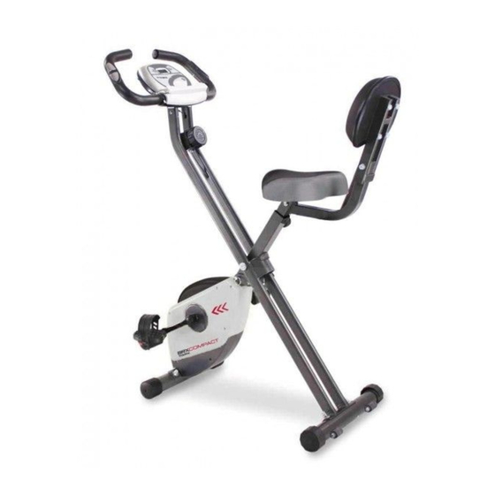
Page 2: Product Overview
ASSEMBLYINSTRUCTIONS RUCTIONS PRODUCT OVERVIEW Handlebar Meter Pulse Sensor Adjustment Knob Back Cushion Back Support Back Frame Top Cover Seat Left Pedal Left Chain Cover End Cap Rear Stabilizer Front Stabilizer Wheel End cap Wheel THEFOLLOWINGTOOLS ARE INCLUDED FOR ASSEMBLY: Wrench Allen Wrench (5mm) w/ Screwdriver... -
Page 3: Hardware Identification Chart
ASSEMBLYINSTRUCTIONS RUCTIONS HARDWARE IDENTIFICATION CHART adyattachedtothepart. Figure Description Carriage Bolt (M8 * 1.25 * 60mm) Carriage Bolt (M8 * 1.25 x*48mm) Bolt, Button Head (M6*1 *40mm) Bolt, Button Head (M6* 12mm) Spring Washer (M6) Acorn Nut (M8*1.25) Arc Washer (M8) Washer (M8) Nut M8 Adjustment Knob... - Page 4 ASSEMBLYINSTRUCTIONS RUCTIONS ASSEMBLY INSTRUCTIONS Place all parts from the box in a cleared area and position them on the floor in front of you. Remove all packing materials from your area and place them back into the box. Do not dispose of the packing materials until assembly is completed.
- Page 5 ASSEMBLYINSTRUCTIONS RUCTIONS STEP 4: Attach the Seat (B24) to the Seat Post (A6) with Nylock Nuts (M8) (D25) and Washer (M8) (D38). Insert the Seat Post (A6) into the Main Frame (A1) and secure with the Adjustment Knob (D1). NOTE: Make sure that the pin on the Adjustment Knob (D1) is inserted into one of the holes in Seat Post (A6).
- Page 6 ASSEMBLYINSTRUCTIONS RUCTIONS STEP7: Insert the Handle Bar (A8) into the Rear Frame (A2) and securing by using the Bolt, Button Head (M6* 12mm) (D52) and Spring Washer (M6)(D53). Then Connecting the Connection Wire (C2) and Sensor (C13).
- Page 7 STEP9: Tighten the Left Strap (B29) and Right Strap (B30) to the Left Pedal (B27) and Right ASSENBLY INSTRUCTIONS Pedal (B28). Lock and tight the Left Pedal (B27) and Right Pedal (B28) on the Left Crank (C5) and Right Crank (C6) by using the Wrench.
-
Page 8: Key Functions
OPERATIONAL INSTRUCITONS KEY FUNCTIONS: MODE: This key lets you to select and lock on to a particular function you want. FUNCTIONS: SCAN: Automatically scans each function of SPEED, DISTANCE,TIME, ODOMETER, CALORIES and PULSE. in sequence, display changes every six seconds. Press and release the button until "SCAN"... -
Page 9: Load Adjustment
LOAD ADJUSTMENT To increase the load, turn the Adjustment Knob (B32) clockwise. To decrease the load, turn the Adjustment Knob (B32) counterclockwise. There are eight levels for the load adjustment. SEAT ADJUSTMENT Proper seat adjustment is important. 1. Turn the Adjustment Knob (D1) to loosen, then pull the Adjustment Knob (D1) to release the pin. - Page 10 STORAGE 1. To store the BIKE, simply keep it in a clean dry place. 2. To avoid damage to the electronics, remove the batteries before storing the BIKE for one year or more. 3. To move the BIKE, hold the HANDLEBAR and tilt the BIKE onto the Wheels of the Stabilizer at the front.
-
Page 11: Product Parts Drawing
PRODUCT PARTS DRAWING TOCONTACTCUSTOMERSERVICE... -
Page 12: Parts List
PARTS LIST TOCONTACTCUSTOMERSERVICE Welding Parts Description Main Frame Rear Frame Front Stabilizer Seat Support Back Frame Back Support Rear Stabilizer Magnetic Bracket Shaft Handlebar Plastic Parts Description Left Chain Cover Right Chain Cover Top Cover Sensor Bracket Bushing Plastic Bushing Plastic Washer Φ8.5*Φ20*2.0T Rubber Cushion Leveling Cap... - Page 13 Stopper Endcap TOCONTACTCUSTOMERSERVICE Bearing Housing Hand grip Grommet Plug Plug Electrical parts Description Meter Connection Wire Left Crank Right Crank Flywheel V-Ribbed Belt (230J) V-Ribbed Belt(240J) Pulley w/ Shaft Pulley Shaft Pulley Sensor Ball Bearing (6000ZZ) Ball Bearing (6200ZZ) Ball Bearing (6003ZZ) Idler Shaft Magnet Idler Shaft...
- Page 14 Bolt, Button Head M8*75 Bolt, Button Head M8*20 TOCONTACTCUSTOMERSERVICE Eye Bolt M6 Screw, Round Head ST4.2*16 Bolt, Round Head (M6*12mm) Wave Washer S10 Screw, Round Head ST4.2*25 Flange Nu M10*1.25 Acorn Nut M8 Arc Washer M8 Washer M8 Nylock Nut M8 Nut M10 U-Shape Bracket Nylock Nut M6...
- Page 15 GARLANDO SPA Via Regione Piemonte, 32 - Zona Industriale D1 15068 - Pozzolo Formigaro (AL) - Italy www.toorx.it - info@toorx.it...
Need help?
Do you have a question about the BRX Compact and is the answer not in the manual?
Questions and answers