Table of Contents
Advertisement
Quick Links
Advertisement
Table of Contents

Related Manuals for TOORX BRX EASY


Summary of Contents for TOORX BRX EASY
- Page 1 INSTRUCTION...
-
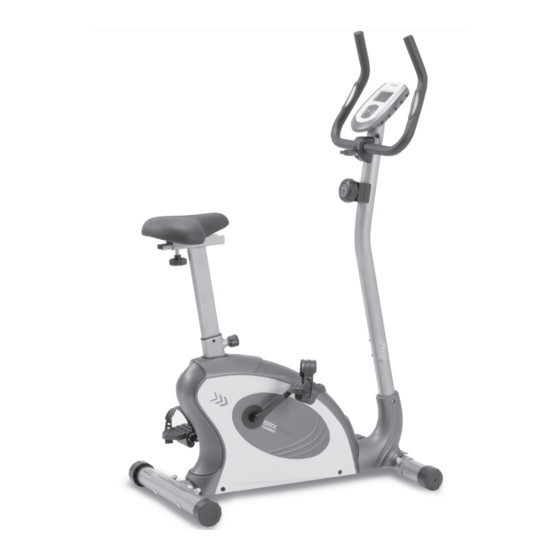
Page 2: Parts List
PARTS LIST Part No. Description Q'ty Main Frame Rear Stabilizer Front Stabilizer End Cap For Rear Stabilizer End Cap For Front Stabilizer Carriage Bolt M10*75 Curve Washer Φ10*Φ22 Domed Nut M10 Quick Release Knob Front Post Tension control w/ upper cable wire Allen Bolt M8*16 Curve Washer Φ8*Φ20 Computer... - Page 3 Magnetic holder Allen bolt M8*55 Magnetic bushing Self-tapping screw ST3*10 BB assembly Flywheel axle Belt pully Hex head bolt M8*45 Hex head nut Spring Idler arm End cap for chain cover Powder spacer Hex head nut M8*16 WasherΦ16.5*Φ12 Bearing 6001 Crank cover Axle of idler Spring...
-
Page 4: Exploded Diagram
EXPLODED DIAGRAM... -
Page 6: Pre-Assembly Check List
PRE-ASSEMBLY CHECK LIST PART NO. DESCRIPTION Q’TY Main Frame F/R Stabilizer Seat Post Seat Handlebar Front Post Computer 39/40 L&R Pedal Plastic Cover for clamp Inner box Manual... -
Page 7: Hardware Parts List
HARDWARE PARTS LIST Description Drawing Q’ty Carriage Bolt M10*75 Curve Washer Φ10*Φ20 Domed Nut M10 Allen Bolt M8*16 Curve Washer Φ8*Φ20 T Type Knob Allen Key L6 Allen Wrench 1 (13/19) Allen Wrench 2 Above described parts are all the parts you need to assemble this machine. Before you start to assemble, please check the hardware packing to make sure they are included. -
Page 8: Assembly Instruction
ASSEMBLY INSTRUCTION STEP 1 Attach front stabilizer (3) to main frame (1), tighten with carriage bolt (6), curve washer (7) and domed nut (8).Then attach rear stabilizer (2) to main frame (1), tighten with carriage bolt (6), curve washer (7) and domed nut (8). STEP 2 ... -
Page 9: How To Connect Tension Connector
HOW TO CONNECT TENSION CONNECTOR Slide the Cable wire from the Upper Tension Connector in between the opening on the wire holder on the Lower Tension Connector. Pull Upper Tension Connector backward and slide the wire through the slot on the bracket. - Page 10 STEP 3 Attach handlebar (15) to front post (10), tighten with a clamp (17) and allen bolt (18), plastic cover (19) and T type knob (20). Connect upper computer wire (34) with middle computer wire (35) ,and connect lower pulse wire (32) with upper pulse wire (33) from the back of the computer (14).
-
Page 11: Check All Bolts And Nuts Are Tightened Before Using The Machine
STEP 5 Attach left pedal strap to left pedal (39) which is marked with decal "L". Doing same for Right Pedal (40). Then attach left pedal (39) and right pedal (40) to their appropriate crank arm (38). The right pedal is on the right hand side of the cycle as you sit on it. Note that the right pedal should be threaded on clockwise and the left pedal on counter-clockwise. -
Page 12: Computer Instructions
COMPUTER INSTRUCTIONS The monitor can only be power on with using the AA batteries. FUNCTION BUTTONS MODE 1. Press the button to select TIME, DISTANCE and CALORIES to preset. 2. Press the button for selection function display value on LCD, or enter after setting. 3. - Page 13 Odometer Display the total accumulated distance from 0.0 to 999.9. User also can press mode key to display the Odometer value. Pulse The monitor will display the user's heart rate in beats per minute during training. Speed Displays your workout speed value in Kilometer per hour. Distance Displays the accumulative distance traveled during each workout up to a maximum of 99.9 MILE.
- Page 14 CARE & MAINTENANCE Proper maintenance is very important to ensure your equipment is always in top working condition. Improper maintenance could cause damage or shorten the life of your equipment and exceed the WARRANTY coverage. Important: Never use abrasives or solvents to clean the equipment. To prevent damage to the computer, keep liquids away and keep it out of direct sunlight.
- Page 15 GARLANDO SPA Via Regione Piemonte, 32 - Zona Industriale D1 15068 - Pozzolo Formigaro (AL) - Italy www.toorx.it - info@toorx.it...
Need help?
Do you have a question about the BRX EASY and is the answer not in the manual?
Questions and answers