Hakko Electronics FM-204 Instruction Manual
Hide thumbs
Also See for FM-204:
- Quick start manual (7 pages) ,
- Instruction manual (84 pages) ,
- Instruction manual (28 pages)
Table of Contents
Advertisement
Quick Links
Advertisement
Table of Contents

Related Manuals for Hakko Electronics FM-204


Summary of Contents for Hakko Electronics FM-204
-
Page 2: Packing List And Part Names
1. PACKING LIST AND PART NAMES Please check to make sure that all items listed below are included in the package. HAKKO FM-204 desoldering station ....1 Iron holder with tip cleaner ......1 MODEL FM-2024 desoldering tool ....1 Handle (for gun confi... -
Page 5: Initial Setup
4. INITIAL SETUP A. Iron holder ● Operation First, remove any excess solder from the tip by thrusting the tip into the cleaning wire. (Do not wipe the tip against the wire. This may cause molten solder to spatter.) 1. Insert the holder assembly securely into the Iron holder base. - Page 6 ● Attaching and replacing the nozzle cartridge Insert the nozzle cartridge fully into the grip as shown in the illustration. Once the nozzle cartridge is inserted, it is locked automatically. Nozzle remover Push CAUTION The nozzle can be very hot. To attach or remove the nozzle cartridge, be sure to use the nozzle remover to preclude the possibility of breaking the grip or cartridge.
- Page 7 2. Put MODEL FM-2024 into the iron holder. V -7 3. Connect the hose from the MODEL FM-2024 to the fi lter case cover on the HAKKO FM-204 Station. 4. Plug the power cord into a grounded wall socket.
-
Page 8: Operation
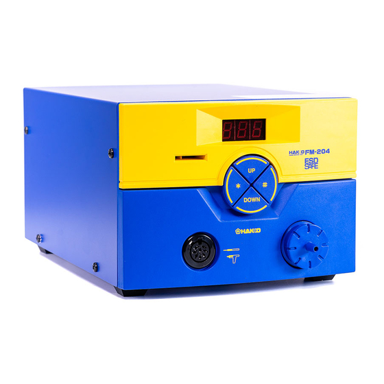
● Temperature scale: ºC or ºF, depending on selection button ● Error detection (See ERROR MESSAGES.) The front panel of the HAKKO FM-204 has four controls. An audible buzzer is provided to alert the operator: ● When the station has reached the set ..End of sequence signal (terminates a... - Page 9 ● Changing the temperature setting • MODEL FM-2024 Insert the card. Temperature setting range ºC ....350 to 450ºC ºF ....660 to 840ºF Press the button. • HAKKO FM-2027 (Option) Temperature setting range ºC ....200 to 450ºC ºF ....400 to 840ºF Press the button once.
- Page 10 The temperature accuracy of iron tips is ±15°C (±27°F) (except for designated tips) when using the default offset values. If a higher temperature accuracy is required, use the following offset function: ● Entering the tip offset value Press the button once. Example: When the set temperature is 400ºC and the actual tip temperature is 410ºC: The...
- Page 11 1. Press and hold the button for at least To change the offset value with the one second. control card in the station: The current offset value is displayed, and then the hundreds digit begins to fl ash one second later.
-
Page 12: Parameter Settings
2 is displayed. CAUTION After the necessary parameters are set, press Do not leave the HAKKO FM-204 for a long time with the and hold the button in steps above auto shutoff function activated. Turn the power off when for two seconds. - Page 13 ● : Auto sleep time setting Set the time until the auto sleep function Turn the power on while pressing button. activates after the soldering iron is set on the iron holder. Press the button. Auto sleep examples: Sleep (immediately after the iron is set on the iron holder) Sleep (10 minutes after the iron is set on the iron holder)
- Page 14 ● : Offset-free mode ● When the station is in the offset-free mode, either is displayed. : The offset value cannot be entered without the control card inserted into the station. : The offset value can be entered without the control card inserted into the station. Select and press the button.
-
Page 15: Maintenance
7. MAINTENANCE Properly maintained, the MODEL FM-2024 desoldering tool should provide years of good service. Effi cient desoldering depends upon the temperature, and the quality and quantity of the solder and fl ux. Perform the following service procedures as dictated by the conditions of the gun’s usage. WARNING Since the desoldering tool can reach a very high temperature, please work carefully. - Page 16 Cleaning the inside of suction pipe CAUTION First remove the nozzle Move the nozzle cartridge to the cleaning f r o m t h e g r i p w h i l e position indicated in fi gure at right. Change the p re s s i n g t h e n o z z l e position of the nozzle cartridge before turning u n l o c k b u t t o n , t h e n...
- Page 17 Checking and replacing the ceramic 1. Turn the filter case cover on the HAKKO FM-204 station counterclockwise to paper fi lter unlock it, then remove the cover by pulling it straight out. The fi lter is clogged with hardened 2. Replace the ceramic paper fi lter.
-
Page 18: Cleaning The Pump
Cleaning the pump WARNING Unplug the power cord before cleaning the pump. NOTE: Consistent replacement of dirty/clogged ceramic fi lters will reduce or eliminate the need to clean the pump. 1) Disassembly 1. Remove the screws (8) used to secure the cover, and remove the cover. - Page 19 ● Checking procedure WARNING Unless otherwise specifi ed, perform the following steps after turning the power switch OFF and disconnecting the AC plug. ■ Checking the cord assembly Checking the electrical continuity of the cord assembly 1. Remove the plug of the cord assembly from the station.
- Page 20 ■ Maintenance This procedure, if followed daily, will materially add to tip life. a. Set the temperature to 250°C (482°F). b. When the temperature stabilizes, clean the tip and check the condition of the tip. If the tip is badly worn or deformed, replace it. c.
-
Page 21: Error Messages
8. ERROR MESSAGES ● Sensor Error When there is the possibility that a failure has occurred in the sensor or heater (including the sensor circuit), is displayed and the power is shut down. NOTE: The sensor error also occurs if the tip is not inserted properly. -
Page 22: Troubleshooting Guide
9. TROUBLE SHOOTING GUIDE WARNING To check inside or replace parts, be sure to turn the power switch OFF and remove the AC plug to avoid electric shock. ● No operation occurs CHECK : Is the power cord connected properly? when the power ACTION : Properly connect the power cable. - Page 23 ● The low-temperature CHECK : Is the setting value for the low-temperature alarm tolerance too low? alarm tolerance error ACTION : Increase the setting value. occurs frequently. ● Heater terminal short CHECK : Is the nozzle cartridge for MODEL FM-2024? ACTION : Turn the power switch OFF and insert the MODEL FM-2024 circuit error...
-
Page 24: Parts List
10. PARTS LIST NOTE: Spare or repair parts do not include mounting screws, if they are not listed on the description. Screws must be ordered separately. Binding head screw M3×6 (8) External tooth lock washer Nominal size 3 (1) Sems screw Sems screw M4×30 (1) M4×8 (4) -
Page 27: Wiring Diagram
● Option Part No. Part Name Specifi cation B3216 Sleeve assembly Yellow B3217 Sleeve assembly Orange B3218 Sleeve assembly Blue B3219 Sleeve assembly Green B3215 Connector cover B2874 Cleaning pin For ø0.6mm (0.02 in.) nozzle B1086 Cleaning pin For ø0.8mm (0.03 in.) nozzle B1087 Cleaning pin For ø1.0mm (0.04 in.) nozzle...
Need help?
Do you have a question about the FM-204 and is the answer not in the manual?
Questions and answers