Hakko Electronics FM-2022 Instruction Manual
Parallel remover, iron holder with a sleep mode
Hide thumbs
Also See for FM-2022:
- Instruction manual (36 pages) ,
- Instruction manual (12 pages) ,
- Instruction manual (12 pages)
Advertisement
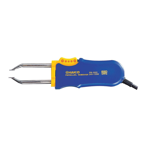
PARALLEL REMOVER
Iron holder with a sleep mode
Instruction Manual
Thank you for purchasing the FM-2022 parallel remover.
Please read this manual before operating the FM-2022. Keep this
manual readily accessible for reference.
• The FM-2022 cannot function by itself. It must be connected to the
FM-203 or FM-206 station.
• Speci昀椀c information can be found in the instruction manual for your
FM-203 or FM-206 station.
TABLE OF CONTENTS
1. PACKING LIST .........................................................1
2. SPECIFICATIONS . ...................................................1
3. WARNINGS, CAUTIONS AND NOTES ...................2
4. PART NAMES . ..........................................................3
5. SETTING UP THE FM-2022 ....................................3
6. OPERATION . ............................................................4
7. MAINTENANCE .......................................................7
8. TROUBLESHOOTING GUIDE .................................8
9. PARTS LIST ...........................................................10
10. WIRING DIAGRAM ................................................11
l
l
CAUTION
Advertisement
Table of Contents

Related Manuals for Hakko Electronics FM-2022


Summary of Contents for Hakko Electronics FM-2022
-
Page 1: Table Of Contents
PARALLEL REMOVER Iron holder with a sleep mode Instruction Manual Thank you for purchasing the FM-2022 parallel remover. Please read this manual before operating the FM-2022. Keep this manual readily accessible for reference. CAUTION • The FM-2022 cannot function by itself. It must be connected to the FM-203 or FM-206 station. • Speci昀椀c information can be found in the instruction manual for your FM-203 or FM-206 station. -
Page 2: Packing List
Heat resistant pad Iron holder Connecting cable l Applicable Models In order to function, the FM-2022 must be connected to the FM-203 or FM-206 station. 2. SPECIFICATIONS l MODEL FM-2022 Parallel remover MODEL FM-2022 Parallel remover Power Consumption 140W (24V) Temperature Range 200 – 400°C (400 – 750°F) Tip to Ground Resistance < 2 Tip to Ground Potential <... -
Page 3: Warnings, Cautions And Notes
NOTE: A NOTE indicates a procedure or point that is important to the process being de- scribed. CAUTION When the power is on, the tip temperature is between 200°C/400°F and 400°C/750°F. Since mishandling may lead to burns or 昀椀re, be sure to comply with the following pre- cautions: l Do not touch the metal parts near the tip. l Do not use the product near 昀氀ammable items. l Advise other people in the work area that the unit can reach a very high tempera- ture and should be considered potentially dangerous. l Turn off the power while taking breaks and when 昀椀nished using the unit. l Before replacing parts or storing the unit, turn off the power and allow the unit to cool to room temperature. CAUTION To prevent damage to the unit and ensure a safe working environment, be sure to comply with the following precautions: l Do not use the unit for applications other than those speci昀椀cally described in the instruction manual. l Do not set the tip temperature higher than 400°C/750°F. l Do not rap the FM-2022 against the work bench to shake off residual solder, or otherwise subject the iron to severe shocks. l Do not modify the unit. l Use only genuine HAKKO replacement parts. l Do not wet the unit or use the unit when your hands are wet. l The operating process will produce smoke. Make sure the area is well ventilated. l Pull on the plug to disconnect the FM-2022 from the station outlet. Do not pull the cord. -
Page 4: Part Names
Fixing flange Plug Handle Cord Tip (not included) Plug Cleaning sponge Heat resistant pad Connecting cable Iron holder 5. SETTING UP THE FM-2022 1. Connector cord NOTE: Pass the connector cord through the hole This product is protected against electro- static discharge and must be grounded for in the heat resistant pad. full ef昀椀ciency. 2. Iron holder When the iron holder is connected with... - Page 5 6. OPERATION l Controls and displays Refer to the FM-203 or FM-206 instruc- tion manual. NOTE: The HAKKO FM-203 has 2 channels; D and S channel. The MODEL FM-2022 can be connected to only the D channel. The HAKKO FM-206 has 3 channels: 1, 2 and 3 channel. MODEL FM-2022 can be con- FM-203 Station nected to only the channel 2. Refer to the HAKKO FM-203/FM-206 instruc- tion manual for details of operating. Channel S Channel D display lamp display lamp Channel D Channel S connector connector l Displays 1. Insert the tips: Hold the head part of the tip with the heat resistant pad and insert the tip into the handpiece. Push until the tip...
- Page 6 l Operating instructions CAUTION: The tip is very hot during operation. 1. Set the Temperature Do not touch the tip or the metal parts near the tip. CAUTION: Very high tip temperatures may damage the printed circuit board, possibly causing the printed pattern to become detached. HAKKO recommends setting the tip temperature be- low 300°C (572°F) for all normal work. Using 2. Apply solder or 昀氀ux the lowest possible effective temper a ture not only helps protect parts that are sensitive to If there is insuf昀椀cient solder on the PWB, heat, it also helps protect the tip from deterio-...
- Page 7 l Control card and changing the tempera- ture setting Please refer to the FM-203 or FM-206 In- struction Manual. l Replacing the tip Removing and inserting the tip: Removing the tip: Hold the handle and pull the tip out of the Hold this part to insert into the tweezer. handpiece with the heat resistant pad. Inserting the tip: Hold head part and insert the tip into the handpiece. Push until the tip stops. Hold the tweezer at the front to remove tip. CAUTION: The tip can be very HOT. Use the heat resis- tant pad for handling hot tips, but do not hold the hot portion of the tip, even with the pad,...
- Page 8 P.16 of the FM-203 instruction manual. If the value still does not decrease, check the connection cord for breakage. n Checking the connection cord 1. Remove the soldering tip and the handle. for breakage (Refer to P.11 2. Measure the resistance values between the WIRING DIAGRAM of B side.) connector and the lead wires at the socket as follows: Pin 1 - Red Pin 2 - Green B side socket Green Black Pin 3 - Black Pin 5 - White If any value exceeds 0Ω or is ∞, replace the FM-2022. White (inside)
- Page 9 2. Measure the resistance values between the WIRING DIAGRAM of A side. ) connector and the lead wires at the socket as follows: Pin 7 - (1) Pin 2 - (3) A side socket Pin 4 - (4) Pin 8 - (2) If any value exceeds 0Ω or is ∞, replace the FM-2022. (2)(inside) 8. TROUBLESHOOTING GUIDE WARNING: Disconnect the power plug before servicing. Failure to do so may result in electric shock. : Is the tip inserted properly? l The tip does not heat CHECK ACTION : Insert the tip completely. : Is the connection cord and/or the CHECK • The sensor error...
- Page 10 : Is the connection cord broken? l The soldering iron error CHECK ACTION : See “Checking the connection cord is displayed. for breakage”. : Is the FM-2022 plug disconnected? CHECK ACTION : Connect the FM-2022. l The low-temperature : Is the tip too small for the items to be CHECK removed? alarm tolerance error ACTION : Use a tip with a large thermal capacity. occurs frequently. : Is the setting value for the low-tem-...
- Page 11 9. PARTS LIST NOTE: Replacement parts do not include mounting screws if they are not listed on the description. Screws must be ordered separately. l Parallel remover Parallel remover Item No. Part No. Part Name Specifications B2783 Handle A & B With screws B2784 LED Holder B2300 Heat resistant pad B3253 Connecting cable l Iron holder Iron holder...
- Page 12 10. WIRING DIAGRAM A side socket + – P.W.B./LED LED1 B side socket Green Black White HEAD OFFICE 4-5, Shiokusa 2-chome, Naniwa-ku, Osaka 556-0024 JAPAN TEL:+81-6-6561-3225 FAX:+81-6-6561-8466 http://www.hakko.com E-mail:sales@hakko.com OVERSEAS AFFILIATES U.S.A.: AMERICAN HAKKO PRODUCTS, INC. TEL: (661) 294-0090 FAX: (661) 294-0096 Toll Free (800)88-HAKKO 4 2 5 5 6 http://www.hakkousa.com...
Need help?
Do you have a question about the FM-2022 and is the answer not in the manual?
Questions and answers