Advertisement
Quick Links
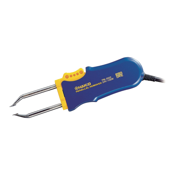
PARALLEL REMOVER
Iron holder with a sleep mode
Instruction Manual
Thank you for purchasing the MODEL FM-2022 parallel re-
mover. Please read this manual before operating the MODEL
FM-2022. Keep this manual readily accessible for reference.
• The MODEL FM-2022 cannot function by itself. It must be con-
nected to an HAKKO FM-203 or FM-206 station.
• Specific information can be found in the instruction manual for
your HAKKO HAKKO FM-203/FM-206 station.
1. PACKING LIST .......................................................25
2. SPECIFICATIONS ..................................................25
3. WARNINGS, CAUTIONS AND NOTES .................26
4. PART NAMES .........................................................27
5. SETTING UP THE MODEL FM-2022 .....................27
6. OPERATION ...........................................................28
7. MAINTENANCE .....................................................31
8. TROUBLESHOOTING GUIDE ...............................32
9. PARTS LIST ...........................................................34
10. WIRING DIAGRAM ................................................35
l
l
CAUTION
TABLE OF CONTENTS
24
Advertisement

Related Manuals for Hakko Electronics FM2022-05


Summary of Contents for Hakko Electronics FM2022-05
-
Page 1: Table Of Contents
PARALLEL REMOVER Iron holder with a sleep mode Instruction Manual Thank you for purchasing the MODEL FM-2022 parallel re- mover. Please read this manual before operating the MODEL FM-2022. Keep this manual readily accessible for reference. CAUTION • The MODEL FM-2022 cannot function by itself. It must be con- nected to an HAKKO FM-203 or FM-206 station. -
Page 2: Packing List
1. PACKING LIST Parallel remover ........1 Iron holder ...........1 Heat resistant pad .......1 Instruction manual .......1 Connecting cable .........1 Tip (not included) MODEL FM-2022 Parallel remover Cleaning sponge Heat resistant pad Iron holder Connecting cable l Applicable Models In order to function, the MODEL FM-2022 must be connected to the HAKKO FM-203/FM-206 soldering station. -
Page 3: Warnings, Cautions And Notes
3.WARNINGS, CAUTIONS AND NOTES Warnings, cautions and notes are placed at critical points in this manual to direct the operator’s attention to significant items. They are defined as follows: WARNING: Failure to comply with a WARNING may result in injury or death. CAUTION: Failure to comply with a CAUTION may result in injury to the opera- tor, or damage to the items involved. -
Page 4: Part Names
4. PART NAMES Button Fixing flange Plug Handle Cord Tip (not included) Plug Cleaning sponge Heat resistant pad Connecting cable Iron holder 5. SETTING UP THE MODEL FM-2022 1. Connector cord Pass the connector cord through the hole in the heat resistant pad. 2. - Page 5 6. OPERATION l Controls and displays Please refer to the HAKKO FM-203 in- struction manual. NOTE: The HAKKO FM-203 has 2 channels; D and S. The FM-2022 can use only the D channel. Refer to the FM-203 instruction manual HAKKO FM-203 for details of operation.
- Page 6 l Operating instructions 1. Set the Temperature CAUTION: The tip is very hot during operation. Do not touch the tip or the metal parts near the tip. 2. Apply solder or flux CAUTION: If there is insufficient solder on the Very high tip temperatures may damage PWB, or the soldered area is too small, the printed circuit board, possibly causing...
- Page 7 l Control card and changing the tempera- ture setting Please refer to the HAKKO FM-203 In- struction manual. l Replacing the tip Removing and inserting the tip: Removing the tip: Hold this part to insert into the tweezer. Hold the handle and pull the tip out of the handpiece with the heat resistant pad.
- Page 8 7. MAINTENANCE l Tip maintenance Please refer to the HAKKO FM-203 Instruction manual. l Checking Procedure WARNING: Unless otherwise directed, carry out these procedures with the power switch OFF and the power UNPLUGGED. 1. Check for a broken heater or sensor n Verify the electrical integrity of the heater and sensor Measure the resistance across this position...
- Page 9 n Checking the connection cord 1. Remove the soldering tip and the for breakage (Refer to P.35 handle. WIRING DIAGRAM of A side. ) 2. Measure the resistance values be- tween the connector and the lead wires at the socket as follows: A side socket Pin 7 - (1) Pin 2 - (3)
- Page 10 l The tip temperature is CHECK : Is the tip contaminated with oxide? ACTION : Remove the oxide by cleaning the tip too low. on a damp sponge of HAKKO 599B tip cleaner. l The soldering iron error CHECK : Is the connection cord broken? ACTION : See “Checking the connection cord is displayed.
- Page 11 9. PARTS LIST NOTE: Replacement parts do not include mounting screws if they are not listed on the description. Screws must be ordered separately. Parallel remover Item No. Part No. Part Name Specifications B2783 Handle A & B With screws B2784 LED Holder B2300...
- Page 12 11. WIRING DIAGRAM A side socket + – P.W.B./LED LED1 B side socket Green Black White HEAD OFFICE https://www.hakko.com 4-5, Shiokusa 2-chome, Naniwa-ku, Osaka 556-0024 JAPAN TEL: +81-6-6561-3225 FAX: +81-6-6561-8466 〒556-0024 大阪市浪速区塩草2丁目4番5号 https://www.hakko.com E-mail: sales@hakko.com T E L : (06) 6561-1574 (代) F AX : (06) 6568-0821 OVERSEAS AFFILIATES U.S.A.: AMERICAN HAKKO PRODUCTS, INC.
Need help?
Do you have a question about the FM2022-05 and is the answer not in the manual?
Questions and answers