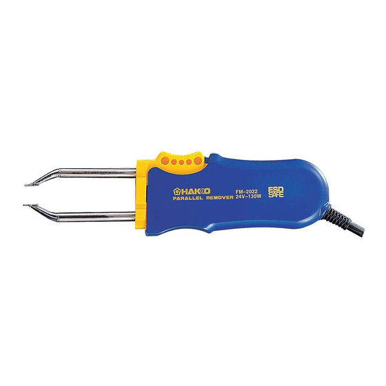
Hakko Electronics FM-2022 Instruction Manual
Parallel remover. iron holder with a sleep mode
Hide thumbs
Also See for FM-2022:
- Instruction manual (12 pages) ,
- Instruction manual (12 pages) ,
- Instruction manual (12 pages)
Table of Contents
Advertisement
Available languages
Available languages
Quick Links
取扱説明書
お買い上げいただきありがとうございます。
この説明書をお読みになり 、 正しくお使いください。
お読みになった後も 、 後日お役に立ちますので
大切に保管しておいてください。
・ MODEL FM-2022 だけでお使いいただくことはできません。
必ずハッコー FM-203 もしくは FM-206 ステーションへ接続し
てお使いください。
・ ハッコー FM-203 もしくは FM-206 ステーションの詳細につい
ては、ハッコー FM-203/FM-206 ステーションの取扱説明書を
ご覧ください。
1. セット内容 ..............................................................1
2. 仕様 ..........................................................................1
3. 安全及び取扱い上のご注意 ...................................2
4. 各部名称 ..................................................................3
5. 組み立て ..................................................................3
6. 使用方法 ..................................................................4
7. メンテナンス ..........................................................7
8. トラブル発生時に ..................................................8
9. 部品リスト ........................................................... 10
10. 配線図 ................................................................... 11
パラレルリムーバー
スリープ機能付こて台
●
●
注 意
Advertisement
Chapters
Table of Contents

Related Manuals for Hakko Electronics FM-2022


Summary of Contents for Hakko Electronics FM-2022
-
Page 1: Table Of Contents
取扱説明書 ● お買い上げいただきありがとうございます。 この説明書をお読みになり 、 正しくお使いください。 お読みになった後も 、 後日お役に立ちますので 大切に保管しておいてください。 ● 注 意 ・ MODEL FM-2022 だけでお使いいただくことはできません。 必ずハッコー FM-203 もしくは FM-206 ステーションへ接続し てお使いください。 ・ ハッコー FM-203 もしくは FM-206 ステーションの詳細につい ては、ハッコー FM-203/FM-206 ステーションの取扱説明書を ご覧ください。 1. セット内容 ..............1 2. 仕様 ................1 3. 安全及び取扱い上のご注意 ........2 4. -
Page 2: セット内容
取扱説明書 �������������������������������������� 1 耐熱パッド �������������������������������������� 1 中継コード �������������������������������������� 1 こて先(別売) MODEL FM-2022 パラレルリムーバー クリーニング スポンジ付 中継コード 耐熱パッド こて台 ● 適用モデル MODEL FM-2022 は必ずハッコー FM-203 もしくは FM-206 ステーションへ 接続してご使用ください。 2. 仕様 ● MODEL FM-2022パラ レルリ ムーバー 消費電力 140 W (24 V) 設定温度範囲 200〜400゜ C こて先アース間抵抗 <2 Ω リーク電圧 <2 mV 接続コー... -
Page 3: 安全及び取扱い上のご注意
取扱いを誤ると、 やけど ・ 火災の恐れがありますので、 以下の注意事項を必ず守っ てください。 ● こて先やこて先周辺の金属部分に触れない。 ● 燃えやすいものの近くで使用しない。 ● 周囲の人に「高温につき危険である」ことを知らせる。 ● 使用を中断・終了する時や、その場を離れる時は電源を切る。 ● 部品交換時や収納時は必ず電源を切り、十分に冷えたことを確認する。 注 意 故障を防ぎ、 作業環境を安全に保つため、 以下の注意事項を必ず守ってください。 ● この取扱説明書で特に説明されている以外の用途に使用しない。 ● こて先設定温度を 400℃より高くしない。 ● はんだかすを取るために、MODEL FM-2022 を作業台に打ちつけるなど強い 衝撃を与えない。 ● 本品を改造しない。 ● 交換部品には 、 純正部品を使用する。 ● 水につけたりぬれた手で使用しない。 ● 使用中に煙が発生するので、十分な換気を行う。 ● コードの抜き差しはプラグを持って行う。... -
Page 4: 各部名称
4. 各部名称 ボタン 固定フランジ プラグ ハンドル コード こて先 (別売) プラグ クリーニング スポンジ付 耐熱パッド こて台 中継コー ド 5. 組み立て 1. 接続コード 接続コードを耐熱パッドの穴に通しま す。 2. こてホルダー ハッコー FM-203 本体とこて台を中継 コードで接続することでスリープ機能 を利用することが可能となります。 ス リ ー プ 時 間 の 設 定 方 法 に 関 し て は ハッコー... -
Page 5: 使用方法
6. 使用方法 ● 操作と表示 ハッコー FM-203 の取扱説明書を参照 してください。 注記: ハ ッ コ ー FM-203 に は D チ ャ ン ネ ル と S チャンネル、2 種類のチャンネルがありま す。この内、FM-2023 が使用できるのはD チャンネルのみです。 詳しい使用方法に関しては FM-203 の取扱 FM-203 ステーション 説明書を参照してください。 D チャンネル S チャンネル 表示ランプ 表示ランプ... - Page 6 ●使用手順 1. 温度を設定する 注意 作業中はこて先が高温になりますのでこて先 と周辺の金属部分は触らないようにしてくだ さい。 注意 2. はんだまたはフラックスを 塗ります。 こて先が高温になりすぎると、プリント基板 を傷めたり、配線パターンがはがれてしまう 基板上のはんだが不十分、またははん ことがあります。通常の作業では、こて先 だ付け部分が小さすぎる場合には、は 温度を 300℃以下に設定するようお薦めしま す。 んだを追加するかフラックスを塗布し 可能な限り低い温度に設定し作業すること てください。こて先側にはんだをのせ で、熱に弱い部品を保護できるだけでなく、 る方法もあります。 熱によるこて先の消耗を抑えることもできま す。 3. はんだを溶かす はんだ付けされた部分にこて先を置き、 はんだを溶かします。はんだが完全に 溶 け た こ と を 確 認 し ま す。 挿 絵「A」 を参照してください。...
- Page 7 ●カードと温度設定の変更 ハッコー FM-203 の取扱説明書を参照 してください。 ●こて先の交換 こて先の取外しと挿入 こて先の取外し: ハンドルを握り、耐熱パッドを使って ハン ドルの前側部分を持って、 こて先を持ち、こて部から引き抜きま こて先を取り外します。 す。 こて先の挿入: こて先の先端部分を持ち、止まるとこ ろまでこて部へ挿入します。 この部分を持ってこて部へ挿入し ます。 注意 こて先は高温になっています。やけどの 原因となりますので、取扱いには十分ご 注意ください。耐熱パッドで熱いこて先 を長時間つかまないでください。...
-
Page 8: メンテナンス
■ 接続コード断線の調べ方 1� こて先とハンドルをはずします。 (11ページの配線図 B 側を参 2� コネクタとソケットリード線の間の抵抗を 照ください) 次の通り測定します。 ピン 1 - 赤 ピン 2 - 緑 B側ソケッ ト 緑 黒 ピン 3 - 黒 ピン5 - 白 ひとつでも抵抗値が 0 Ωより大きいか、ま たは∞の場合、MODEL FM-2022 を交換 白 (内側) してください。 赤 ... -
Page 9: トラブル発生時に
2� コネクタとソケットリード線の間の抵抗を 照ください) 次の通り測定します。 ピン 7 - (1) ピン 2 - (3) A側ソケ ッ ト ピン 4 - (4) ピン 8 - (2) ひとつでも抵抗値が 0 Ωより大きいか、ま たは∞の場合、MODEL FM-2022 を交換 (2) 内側 してください。 8. トラブル発生時に 警告 修理を実施する際、電源プラグは必ず抜いてください。 感電の恐れがあります。 ● こて先が熱くならない。 : こて先はしっかりと差し込まれてい... - Page 10 : はんだ除去対象物に対してこて先が小 点検 さすぎませんか。 が頻発する。 対処 : 「接続コード断線の調べ方」の項を参照 してください。 : 下限設定温度エラーの設定が低すぎま 点検 せんか。 対処 : 設定値を大きくしてください。 ● ヒーター端子短絡エ : こて先は MODEL FM-2022 用ですか。 点検 ラーを示す が表 対処 : 電源スイッチを切り、 間違いなくMOD- 示される。 EL FM-2022 こて先を挿入し、電源ス イッチを入れ直してください。 ● こて先を閉じることが : こて先同士の間に異物が挟まっていま 点検 できない。...
-
Page 11: 部品リスト
9. 部品リスト 注記: 取付けねじは、仕様欄に記載されていない場合、交換 部品には含まれていません。別途ご注文ください。 パラレルリムーバー 図番 品番 部品名 仕様 ハウジング、AとB ねじ付き B2783 LEDホルダー B2784 耐熱パッド B2300 中継ケーブル B3253 こて台 仕様 図番 品番 部品名 クリーニングスポンジ付き FH200-03 こて台 こて台部品 図番 品番 部品名 仕様 こて台ベース ゴム足付き B3251 クリーニングベース B3249 ステー B3250 スイッチケース組品 B3252 こてホルダー(組品)... -
Page 12: 配線図
10. 配線図 A側ソケット + – 基板/表示用 LED1 B側ソケット 緑 黒 赤 白... - Page 13 使用 MODEL FM-2022 前,請詳閱 本 使用說明書,正確使用。 閱後請妥為收存,以備日後查閱。 ● 注 意 ● MODEL FM-2022 無法單獨使用。請務必接續 HAKKO FM-203 或 FM-206 控制臺使用之。 ● 關於 HAKKO FM-203 或 FM-206 控制臺之詳細,請參閱 HAKKO FM-203 或 FM-206 控制臺之使用說明書。 目 錄 1. 包裝清單 ..........13 2. 規格 ............ 13 3.
-
Page 14: 包裝清單
1. 包裝清單 平行除錫鑷子 ..........1 焊鐵座 ............1 抗熱墊片............1 使用說明書 ..........1 中繼線 ............1 ● 適用機種 FM-2022請務必接續HAKKO FM-203 或 FM-206控制臺使用。 2. 規格 注意 : 本產品施有防靜電措施,對塑膠導電性,並對焊鐵部與機身部作接地,請特別留意下列注意事項 : 1. 手柄等之塑膠,並非絕緣物,而是有導電性塑膠,修理時請十分注意之。進行部件更換或修理時, 有電部分不可露出,及切勿損傷絕緣材料。 2. 請務必接地使用之。... -
Page 15: 安全及使用上的注意事項
當電源接通時,焊鐵頭溫度會達到攝氏 200 ∼ 450℃的高溫。 ● 切勿碰觸焊鐵頭或其周圍的金屬部分。 ● 切勿在易燃物附近使用本機器。 ● 通知周圍的人「高溫危險」 。 ● 使用暫停、結束或要離開時應關掉電源。 ● 更換部件或收起本機器之前,應關掉電源,並待機器冷卻至室溫。 注 意 為了防止故障並維護作業環境安全起見,請務必遵守以下之注意事項。 ● 本使用說明書所特別說明以外之用途,不加以使用。 ● 不使焊鐵頭設定溫度高於 400℃。 ● 不將 MODEL FM-2022 敲打作業台等試圖以強力衝擊去除焊錫屑。 ● 切勿改裝本產品。 ● 更換部件時,必僅使用 HAKKO 正廠部件。 ● 切勿弄濕本產品或以濕手使用。 ● 使用中會產生煙霧,請充分做好通風。 ● 拔出電線時,請抓住插頭。切勿拉住電線。... -
Page 16: 各部名稱
中繼線 5. 組裝 1. 電線組件 將電線組件穿過抗熱墊片之孔。 2. 焊鐵座 使用省電源機能時 , 請將中繼線連接到 焊鐵座和 焊鐵控制臺背面的插座上。 請參照 MODEL FM-2022 之使用說明書。 3. 接續 中継コード 1. 將插頭接續到 HAKKO FM-203 之插座。 中繼線 2. 將 MODEL FM-2022 置於焊鐵座上。 3. 將電源線之插頭插入電源座。請務必 做好接地。 註 : MODEL FM-2022 實施防靜電處理,所以 務必請接地之後再使用,以充分發揮功效。... -
Page 17: 使用方法
6. 使用方法 ●控制與顯示 請參照 HAKKO FM-203 之使用說明書。 註 : HAKKO FM-203 有二個路徑 您能把 MODEL FM-2022 機型連接到 D 接 口路徑 請參照 HAKKO FM-203 之使用說明書。 HAKKO FM-203 控制臺 D 路徑顯示燈 S 路徑顯示燈 D 路徑接口 S 路徑接口 ●顯示 1. 插入焊鐵頭。 使 用 抗 熱 墊 片 拿 著 焊 鐵 頭 之 鐵 頭 部... - Page 18 ●使用程序 1. 設定溫度 注意 : 操作時焊鐵頭溫度會昇高,切勿接觸焊鐵頭 及其周圍的金屬部分。 2. 塗抹焊錫或焊劑。 注意 : 基板上沒有充足之焊錫,或焊錫黏著部 焊鐵頭溫度變為太高的話,會傷及印刷電路 份太小時, 請在基板上塗抹焊錫或焊劑。 板,可能使所印刷電路線圖樣斷掉。通常之 作業中,HAKKO 建議您將焊鐵頭溫度設定 焊鐵頭上亦可塗抹焊錫。 為低於 300℃之溫度。設定成可能之最低效 率溫度的話,不僅可保護耐熱較弱之部件, 並有幫助於防熱度造成鐵頭惡化。 3. 溶解焊錫 將焊鐵頭置於焊錫黏著部份, 溶解焊錫。 確認焊錫已完全溶解。請參照插圖 「A」 。 4. 取下部件 確認焊錫已完全溶解之後,輕輕握緊焊 鐵部,抓住部件提起而取下。請參照插 圖「B」 。...
- Page 19 ●插卡與溫度設定之更換 請參照 HAKKO FM-203 的使用說明書。 ●更換焊鐵頭 取下或插入焊鐵頭 取下焊鐵頭 : 握住手柄,使用抗熱墊片拿著焊鐵頭, 將焊鐵頭自焊鐵部拔出。 插入焊鐵頭 : 拿著焊鐵頭之尖端部份,將焊鐵頭插入 焊鐵部。焊鐵頭一直推到無法再進入為 止。 注意 : 焊鐵頭會很燙。可能引起燙傷,使用時請 充分注意。 請勿以抗熱墊片拿焊鐵頭太久。...
-
Page 20: 保養
3. 電阻值超過 2 歐姆(常溫時)時,請 實行 HAKKO FM-203 使用說明書之第 44 頁的檢查和清理焊鐵頭。如果還是 無法降低,請檢查組裝電線是否斷線。 ■ 組裝電線破損檢查方法 1. 取下焊鐵頭與手柄。 (請參照第 23 頁電路圖的B側 2. 測定插頭接腳與套管引線之間的電阻 套管) 值。 接腳 1– 紅 接腳 2– 綠 接腳 3– 黑 接腳 5– 白 電阻值比 0Ω 大,或無限大(∞)時, 請更換 MODEL FM-2022 。... -
Page 21: 排除故障指南
1. 取下焊鐵頭與手柄。 (請參照第 23 頁電路圖的A側 2. 測定插頭接腳與套管引線之間的電阻 套管) 值。 接腳 7-(1) 接腳 2-(3) 接腳 4-(4) 接腳 8-(2) 電阻值比 0Ω 大,或無限大(∞)時, 請更換 MODEL FM-2022 。 8. 排除故障指南 警告 : 進行修理時,請務必拔掉電源插頭,否則可 能造成觸電。 ●焊鐵頭無法加熱。 檢查 : 焊鐵頭插入正確嗎 ? 動作 : 請完全插入。 ·傳感器錯誤 被顯示。... - Page 22 ●表示發熱元件端子短路 檢查 : 焊鐵頭是 MODEL FM-2022 用的嗎 ? 動作 : 請 關 閉 電 源 開 關, 正 確 插 入 錯誤之 被顯示。 MODEL FM-2022 焊 鐵 頭, 再 重 新打開電源開關。 ●焊鐵頭無法關閉。 檢查 : 焊鐵頭彼此之間夾有異物嗎 ? 動作 : 請去除異物。 ·焊鐵頭無法回到原來位置。...
-
Page 23: 部件清單
9. 部件清單 註 : 安裝螺絲如果在規格表內沒有記載的話,不含於更 換部件內,請另外訂購。... -
Page 24: 電路圖
10. 電路圖... - Page 25 FM-2022. Keep this manual readily accessible for reference. CAUTION • The MODEL FM-2022 cannot function by itself. It must be con- nected to an HAKKO FM-203 or FM-206 station. • Specific information can be found in the instruction manual for your HAKKO HAKKO FM-203/FM-206 station.
-
Page 26: Packing List
Heat resistant pad Iron holder Connecting cable l Applicable Models In order to function, the MODEL FM-2022 must be connected to the HAKKO FM-203/FM-206 soldering station. 2. SPECIFICATIONS l MODEL FM-2022 Parallel remover Power consumption 140 W (24 V) Temperature range 200 –... -
Page 27: Warnings, Cautions And Notes
Do not set the tip temperature higher than 400°C. l Do not rap the MODEL FM-2022 against the work bench to shake off residual solder, or otherwise subject the iron to severe shocks. l Do not modify the unit. -
Page 28: Part Names
3. Connections 1. Connect the plug to the HAKKO Connecting cable FM-203. 2. Place the MODEL FM-2022 in the When the plug ‘clicks’, iron holder. it is fully inserted. Receptacle 3. Plug the power cord into the power supply. - Page 29 Controls and displays Please refer to the HAKKO FM-203 in- struction manual. NOTE: The HAKKO FM-203 has 2 channels; D and S. The FM-2022 can use only the D channel. Refer to the FM-203 instruction manual HAKKO FM-203 for details of operation.
- Page 30 l Operating instructions 1. Set the Temperature CAUTION: The tip is very hot during operation. Do not touch the tip or the metal parts near the tip. 2. Apply solder or flux CAUTION: If there is insufficient solder on the Very high tip temperatures may damage PWB, or the soldered area is too small, the printed circuit board, possibly causing...
- Page 31 l Control card and changing the tempera- ture setting Please refer to the HAKKO FM-203 In- struction manual. l Replacing the tip Removing and inserting the tip: Removing the tip: Hold this part to insert into the tweezer. Hold the handle and pull the tip out of the handpiece with the heat resistant pad.
- Page 32 B side socket Green Black Pin 1 – Red Pin 2 – Green Pin 3 – Black Pin 5 – White If any value exceeds 0Ω or is ∞, re- White (inside) place the MODEL FM-2022.
- Page 33 Pin 2 - (3) Pin 4 - (4) Pin 8 - (2) If any value exceeds 0Ω, replace the (2)(inside) MODEL FM-2022. 8. TROUBLESHOOTING GUIDE WARNING: Disconnect the power plug before servicing. Failure to do so may result in electric shock.
- Page 34 Heater terminal short CHECK : Is the tip for FM-2022? ACTION : Turn the power switch OFF and in- circuit error sert the correct FM-2022 tip. Turn the displayed. power switch ON. l The tips cannot be CHECK : Is there a foreign object between the tips? closed.
- Page 35 9. PARTS LIST NOTE: Replacement parts do not include mounting screws if they are not listed on the description. Screws must be ordered separately. Parallel remover Item No. Part No. Part Name Specifications B2783 Handle A & B With screws B2784 LED Holder B2300...
- Page 36 11. WIRING DIAGRAM A side socket + – P.W.B./LED LED1 B side socket Green Black White HEAD OFFICE https://www.hakko.com 4-5, Shiokusa 2-chome, Naniwa-ku, Osaka 556-0024 JAPAN TEL: +81-6-6561-3225 FAX: +81-6-6561-8466 〒556-0024 大阪市浪速区塩草2丁目4番5号 https://www.hakko.com E-mail: sales@hakko.com T E L : (06) 6561-1574 (代) F AX : (06) 6568-0821 OVERSEAS AFFILIATES U.S.A.: AMERICAN HAKKO PRODUCTS, INC.
Need help?
Do you have a question about the FM-2022 and is the answer not in the manual?
Questions and answers