
Related Manuals for Interlogix TruVision 4 Series


Summary of Contents for Interlogix TruVision 4 Series
-
Page 1: Camera Installation
TruVision Series 4 IP Camera Installation Guide P/N 1073195-EN • REV E • ISS 15MAY19... - Page 2 Copyright © 2019 United Technologies Corporation, Interlogix is part of UTC Climate, Controls & Security, a unit of United Technologies Corporation. All rights reserved. Trademarks and Trade names used in this document may be patents trademarks or registered trademarks of the manufacturers or vendors of the respective products.
- Page 3 interference. (2) This Device must accept any interference received, including interference that may cause undesired operation. ACMA compliance Notice! This is a Class A product. In a domestic environment this product may cause radio interference in which case the user may be required to take adequate measures.
- Page 4 2012/19/EU (WEEE directive): Products marked with this symbol cannot be disposed of as unsorted municipal waste in the European Union. For proper recycling, return this product to your local supplier upon the purchase of equivalent new equipment, or dispose of it at designated collection points.
- Page 5 Contact information For contact information go to: www.interlogix.com and manuals or www.firesecurityproducts.com To get translations for this and other product manuals go to: www.firesecurityproducts.com...
-
Page 7: Table Of Contents
Content Introduction 2 Product overview 2 Installation 3 Installation environment 3 Package contents 4 Cable requirements 10 Camera description 12 Setting up the camera 16 IR illuminators 17 Accessing the SD card 18 Mounting the bullet camera 18 Mounting the VF mini dome camera 19 Mounting the outdoor dome camera 25 Using the camera with a TruVision recorder or another system 30... -
Page 8: Introduction
Introduction Product overview This is the installation guide for TruVision Series 4 IP camera models: TVC-5401 (2MPX IP box camera) TVC-5402 (3MPX IP box camera) TVC-5403 (5MPX IP box camera) TVB-5401 (2MPX IP bullet camera, 2.8 to 12 mm) ... -
Page 9: Installation
Installation This section provides information on how to install the cameras. Installation environment When installing your product, consider these factors: • Electrical: Install electrical wiring carefully. It should be done by qualified service personnel. Always use a proper PoE switch or a 12 VDC UL listed Class 2 or CE certified power supply to power the camera. -
Page 10: Package Contents
Cleaning: Do not touch the sensor modules with fingers. • If cleaning is necessary, use a clean cloth with some ethanol and wipe the camera gently. If the camera will not be used for an extended period of time, put on the lens cap to protect the sensors from dirt. - Page 11 Installation manual • IP VF bullet camera Camera Back box • • Template Screws M4.8 × 18 • • (4 pcs) to attach the back box Installation Guide...
- Page 12 Screws (4 pcs) Water joint: Provide • • water resistance to network connection CD with Configuration Wrench • • manual and TruVision Device Manager Plastic G3/4 cable WEEE and Battery • • adapter Disposal sheets Installation Guide...
- Page 13 Installation manual • IP VF mini dome camera Camera Adaptor: for TVD-CB3 • • cup base Template Screws (4 pcs) • • Installation Guide...
- Page 14 Hex wrench CD with Configuration • • manual and TruVision Device Manager Installation manual WEEE and Battery • • Disposal sheets IP VF outdoor dome camera Camera Back box • • Installation Guide...
- Page 15 Template (flush mount) Template (back box) • • Drill Template Screws (4 pcs) Screws: 4 × 75 mm • • (3 pcs) Screws M4 × 9.5 Wrench • • (3 pcs) to attach the back box Alarm connector (4 pcs) Water joint: Provide •...
-
Page 16: Cable Requirements
Installation manual CD with Configuration • • manual and TruVision Device Manager WEEE and Battery Plastic G3/4 cable • • Disposal sheets adapter CAUTION: Use direct plug-in UL listed power supplies marked Class 2/CE certified or LPS (limited power source) of the required output rating as listed on the unit. - Page 17 Table 1 below lists the requirements for the cables that connect to the camera. Table 1: Recommended power cable requirements Box camera: 12 VDC/24 VAC power wires or PoE (802.3af) VF bullet camera: 12 VDC power wires or PoE+ (802.3at) VF mini dome: 12 VDC power wires or PoE (802.3af) VF outdoor dome:...
-
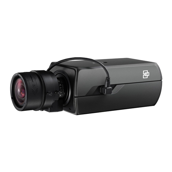
Page 18: Camera Description
Camera description Figure 1: IP bullet camera GND AUX Ethernet RJ45 PoE port Aux Power Port (AUX&GND) Power supply RS-485 port Reset button 10. Alarm In SD card slot 11. Audio Out BNC port 12. ABF (automatic back Ground focus) button Alarm Out 13. - Page 19 Note: To reset the camera to default settings, press and hold the RESET button and power on the camera. After the camera is started up, please hold the Reset button for an additional 20 seconds. The type of auto-iris interface is shown below: DC-driven Damp- Damp+...
- Page 20 Figure 2: IP VF bullet camera Light sensor Power supply Lens Alarm I/O Shield 10. Audio output Mounting base 11. Audio input DC 12V output Reset button BNC output 13. SD card slot Ethernet RJ45 PoE port 14. Serial port Installation Guide...
- Page 21 Figure 3: IP VF mini dome camera Dome liner Serial port Bubble Assembly SD card slot Lens Adaptor BNC port 10. Knockout Reset button 11. Camera terminals Status indicator Installation Guide...
-
Page 22: Setting Up The Camera
Figure 4: IP VF outdoor dome camera Dome liner Power supply Bubble Assembly Lens SD card slot Alarm I/O, 12 V AUX output and Audio I/O Video output 10. BNC output Reset button 11. Back box Ethernet RJ45 PoE port Setting up the camera Note: If the light source where the camera is installed... -
Page 23: Ir Illuminators
To quickly put the camera into operation: Prepare the mounting surface. Mount the camera on the mounting surface using the appropriate fasteners. See “Mounting the bullet camera” on page 18. Set up the camera’s network and streaming parameters so that the camera can be controlled over the network. For further information, please refer to the “TruVision Series 4 IP Camera Configuration Manual”. -
Page 24: Accessing The Sd Card
Accessing the SD card Insert a Micro SD card with up to 128GB to use the camera as an additional recording device, or as a backup in case of failure of communication with the network video recorder (see Figure 1 on page 12). The card is not supplied with the camera. -
Page 25: Mounting The Vf Mini Dome Camera
Hook the camera to the back box with the safety cable. Use the screws to fix the camera to the back box. Mounting the VF mini dome camera To mount the VF dome camera on a ceiling or wall: Loosen the three screws on the edge of the lower dome with a wrench. - Page 26 Using the drill template, drill the holes in the mounting surface. Screw holes Cable holes If you want to route the cables behind the dome, drill a cable hole in the ceiling or wall using the drill template. (Optional) Routing the cable from the side knockout instead of the cable hole drilled on the ceiling is Installation Guide...
- Page 27 supported. Use a pliers to remove the knockout plug shown in the figure below, and route the cables from the knockout. Knockout Fix the adapter plate to the ceiling with the supplied screws. Align the mounting base with the adapter plate and route the mounting base counterclockwise to fit it to the adapter plate.
- Page 28 Lock screw Adjust the viewing angle according to the figure below. Panning angle [0~80°], tilting angle [0~355°], and azimuth angle of the lens [0~355°]. Adjust the focus and zoom. Connect the VIDEO OUT interface of the camera to the event monitor. Set the iris type to MANUAL.
- Page 29 Adjust the No.1 Zoom Lever (T~W) to select a proper angle of view. Adjust the No.2 Focus Lever (F~N) to obtain the desired image quality on the monitor. Set the iris type as MANUAL if the environment has a good and stable illumination. Set the iris type as AUTO if the environment has varied levels of illumination.
- Page 30 Dome drive Black liner Bubble 11. Tighten the lock screw to complete the installation. Installation Guide...
-
Page 31: Mounting The Outdoor Dome Camera
Mounting the outdoor dome camera To mount the outdoor dome camera on a ceiling: Drill the screw holes on the ceiling with the supplied drilling template. To route the cables from the base of the camera, cut a cable hole in the ceiling. Install the mounting base to the ceiling with the supplied screws. - Page 32 Install the dome camera to the mounting base. Adjust the viewing angle. Loosen the lock screw beside the lens. Hold the plastic plate and rotate the camera to adjust the panning angle [0~350°]. Push the lens forward and backward to adjust the tilting angle [0~80°].
- Page 33 Rotate the lens to adjust the azimuth angle of the camera [0~350°]. Tighten the lock screw. Tilt 80° Pan 350° Rotation 350° Re-attach the dome liner and bubble to the camera. To mount the outdoor dome camera into a ceiling: Drill the screw holes on the ceiling with the supplied drilling template.
- Page 34 Drill Template Remove the housing and liner from the camera. Secure the camera to the holes with three screws. Installation Guide...
- Page 35 Re-attach the housing and liner. Installation Guide...
-
Page 36: Using The Camera With A Truvision Recorder Or Another System
Using the camera with a TruVision recorder or another system Please refer to the NVR/DVR user manuals for instructions on connecting and operating the camera with these systems. Using the camera with TruVision Navigator A camera can either be connected to a TruVision, or it can be added directly to TruVision Navigator. -
Page 37: Truvision Ip Vf Bullet Dome
TruVision IP VF bullet dome Electrical Voltage input 12 VDC, PoE+ (IEEE 802.3at) Power consumption Max. 13 W Miscellaneous Connectors Audio In/Out, Alarm In/Out, 12 VDC Power Input, Network Port (PoE), CVBS Output, AUX Power Output Operating temperature -40 to +60 °C (-40 to +140 °F) Dimensions Ø... -
Page 38: Truvision Ip Vf Outdoor Dome Cameras
Dimensions Ø 140 × 121.8 mm (Ø 5.51 × 4.80 in.) Weight 1400 g (3.09 lbs.) Environmental rating IK10 TruVision IP VF outdoor dome cameras Electrical Voltage input 12 VDC/24 VAC, PoE+ (IEEE 802.3at) Power consumption Max. 17 W Miscellaneous Connectors Network Port(PoE), 12 VDC/24 VAC Power Input, Aux Power... -
Page 39: Pin Definitions
Pin definitions There are eight wires on a standard UTP/STP cable and each wire is color-coded. The following shows the pin allocation and color of straight and crossover cable connection: Figure 5: Straight-through cable White/Orange White/Orange Orange Orange White-Green White-Green Blue Blue White/Blue... - Page 40 Please make sure your connected cables have the same pin assignment and color as above before deploying the cables in your network. Installation Guide...
Need help?
Do you have a question about the TruVision 4 Series and is the answer not in the manual?
Questions and answers