
Subscribe to Our Youtube Channel
Related Manuals for HPE SimpliVity 2600 Gen10


Summary of Contents for HPE SimpliVity 2600 Gen10
- Page 1 Hewlett Packard Enterprise HPE SimpliVity 2600 Gen10 Installation and Maintenance Guide Part number: P07987-002 Published: September 2018...
- Page 2 © 2018 Hewlett Packard Enterprise Development LP Notices The information contained herein is subject to change without notice. The only warranties for Hewlett Packard Enterprise products and services are set forth in the express warranty statements accompanying such products and services. Nothing herein should be construed as constituting an additional warranty. Hewlett Packard Enterprise shall not be liable for technical or editorial errors or omissions contained herein.
-
Page 3: Table Of Contents
Contents Chapter 1: Component identification............ 5 HPE SimpliVity 2600 Gen10 server components................. 5 Front panel components..................... 6 Back panel components - HPE SimpliVity 170 Gen10 server..........8 Back panel components - HPE SimpliVity 190 Gen10 server..........9 Specifications..........................11 Vibration and shock......................11 Agency compliance...................... - Page 4 Chapter 6: Power supply maintenance..........30 Power supply maintenance guidelines..................30 Replace a power supply......................30 Chapter 7: Network cabling options........... 32 10 GbE-only network configuration.....................32 Switch-connected network configuration..................33 Appendix A: Support and other resources........35 Support and other resources...................... 35 Accessing Hewlett Packard Enterprise Support............... 35 Accessing updates......................
-
Page 5: Chapter 1: Component Identification
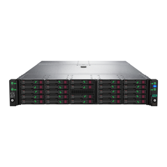
Information Library: http://www.hpe.com/info/simplivity2600-Gen10-docs. HPE SimpliVity 2600 Gen10 server components The HPE SimpliVity 2600 Gen10 chassis accomodates up to four 1U HPE SimpliVity 170 Gen10 servers or two 2U HPE SimpliVity 190 Gen10 servers based on storage and processor requirements. ®... -
Page 6: Front Panel Components
Media Module Adapter: Provides a 1 GbE 2-port interface for the HPE SimpliVity Management network. PCI slot 2: 10 GbE 2-port NIC for storage, HPE SimpliVity Federation network, and optionally HPE SimpliVity Management. An optional 4- port 1 GbE NIC is available. - Page 7 Each server has a capacity of up to 6 drives. System Information Card Provides server identification information that might be required when contacting Customer Support (support.hpe.com). Drive position diagram Provides the front drive numbering and location. Chapter 1: Component identification...
-
Page 8: Back Panel Components - Hpe Simplivity 170 Gen10 Server
Back panel components - HPE SimpliVity 170 Gen10 server The HPE SimpliVity 2600 Gen10 chassis supports up to four HPE SimpliVity 170 Gen10 servers. Each server requires management and data connections and provides LED status indicators. The following graphic shows the components for one server, but the components are identical for all four. -
Page 9: Back Panel Components - Hpe Simplivity 190 Gen10 Server
Back panel components - HPE SimpliVity 190 Gen10 server The HPE SimpliVity 2600 Gen10 chassis supports two HPE SimpliVity 190 Gen10 servers. Each server requires management and data connections. Each server is 2U in height and has the capability to accommodate an optional NIC or GPU accelerator. - Page 10 Pull tab Provides server serial number and iLO label. Media Module Adapter 1 GbE Media Module Adapter containing two ports numbered 1 and 2, from left to right for the HPE SimpliVity Management network. Power button/LED Solid green = System on...
-
Page 11: Specifications
See the product QuickSpec for the latest information on system specifications. Vibration and shock The server configured for deployment in a HPE OmniStack federation does not exceed the vibration and shock limit specifications for a fully-configured server. Agency compliance HPE SimpliVity 2600 Gen10 servers, when configured for deployment in an HPE OmniStack federation, meet the same compliance standards as standard HPE Apollo Gen10 servers. -
Page 12: Chapter 2: Install The Chassis Components
Shipping carton contents The shipping carton contains standard items and other items based on your configuration. Part Description Chassis HPE SimpliVity 2600 chassis. Servers (two, three, or four) Provide processing power and storage capacity. Power cords • Two standard power cords that meet one of the following specifications based on power requirements: •... -
Page 13: Components Not Supplied In The Shipping Carton
Safety, Compliance, and Warranty Information. • Start Here Options Installation Information. • Start Here information for the HPE SimpliVity 2600 Gen10 system. Components not supplied in the shipping carton Your network environment might require additional components not supplied in the shipping carton. -
Page 14: Rack Requirements
Before installing the chassis into the rack, Hewlett Packard Enterprise recommends removing the servers and drives. Because a fully populated chassis is heavy, removing these components facilitates moving and installing the chassis. For instructions, refer to the HPE Apollo 2000 Gen10 Chassis User Guide available from the http://support.hpe.com website. - Page 15 IMPORTANT: When installing each chassis into the rack, be sure that the HPE Apollo Platform Manager is at the top of the chassis to ensure proper orientation in the rack. Start installing the chassis at the lowest available U space in the rack.
-
Page 16: Connect The Power Cables
Connect the network cables Procedure overview Each of the HPE SimpliVity 2600 Gen10 servers in the HPE SimpliVity 2600 Gen10 chassis provide 10 GbE and 1 GbE network interfaces for the Federation, Storage, and Management network traffic. You can access the following network interfaces at the back of the servers: •... -
Page 17: Power Up The Server
Procedure 1. Connect the cables according to the guidelines for the HPE SimpliVity 2600 Gen10 networks only. 2. Ensure that no other network interfaces, such as optional 10 GbE interfaces, are connected to your network before deploying the server to a federation. - Page 18 3. Watch the health indicator (2) on the front panel to make sure it changes from flashing green to steady green. NOTE: If an error occurs during server start-up, contact Customer Support (support.hpe.com). 4. Repeat the above steps for each server in the chassis.
-
Page 19: Chapter 3: Configure The Ilo Port For Remote Management
NOTE: If you prefer to configure iLO at a later time, you can skip this task and deploy the server using Deployment Manager. See the HPE OmniStack 3.7.6 for vSphere Deployment Guide for deployment instructions. Procedure overview You configure the iLO port on each server in the chassis to access the iLO console through a web browser. The iLO console provides out-of-band remote server management and access to advanced management options. -
Page 20: Connect To Ilo And Launch The Integrated Remote Console (Irc)
Procedure overview You connect to iLO through a web browser to launch the remote console. iLO supports Java, .NET IRC, HTML5, and the HPE iLO Mobile application for remote access. Procedure Chapter 3: Configure the iLO port for remote management... - Page 21 1. Log in to any computer that can access the IP address for the iLO web interface. 2. Enter the iLO IP address into your browser. For example: http://192.168.0.120 3. If you haven't changed the default settings, use the default user name and password found on the pull out tag attached to the rear of the chassis to log in.
-
Page 22: Chapter 4: Server Troubleshooting
Customer Support (support.hpe.com). Diagnostic indicators The front panel on the HPE SimpliVity 2600 Gen10 chassis provides diagnostic LEDs that indicate when each server is functioning properly and when a hardware-related error occurs. The indicators can help you correct problems before they affect service levels. -
Page 23: Drive Monitoring
The LEDs on the front of each drive indicate when a drive has failed or is failing. If a drive fails, contact Customer Support (support.hpe.com) to obtain a replacement drive of the same type, size, and speed. The drives in the front panel store user and federation data and are protected by RAID 1+0 and RAID 5. -
Page 24: Front Drive Numbering
4-6. An HPE SimpliVity 190 Gen10 system consists of two 2U servers supporting a total of 12 drives in the chassis. Server 1 uses drives 1-1 through 1-3 and drives 2-1 through 2-3. Server 3 uses drives 3-1 through 3-3, and 4-1 through 4-3. -
Page 25: Power Supply Monitoring
This example shows the interface locations for server 3 (in a chassis with 3 nodes) only, for ease of viewing. All servers have identical interface locations. Optional NICs for guest VM networks may be installed in the HPE SimpliVity 190 Gen10 system. - Page 26 For minimum configurations, you can use only the 10 GbE interfaces to provide a single redundant path for all three networks: Storage, Federation, and Management. However, you must use VLANs to separate the networks as described in the HPE OmniStack for vSphere Client Administrator Guide. Interface...
- Page 27 Interface State Connection active Solid green 1 GbE Link No link detected (cable disconnected) Link connection active Solid green Chapter 4: Server troubleshooting...
-
Page 28: Chapter 5: Drive Maintenance
• • Keep shipping material. Return a failed drive to Customer Support (support.hpe.com) in the packaging in which the replacement drive was shipped. Shipping drives in unauthorized packaging may void your warranty. Drive replacement requires a RAID rebuild, which might take some time to complete on a server that contains many GB or TB of data. - Page 29 • Read the guidelines for protecting components from electrostatic discharge (ESD). • Verified that no backup operations are running. Procedure overview You replace a solid state drive (SSD) that has failed, or is failing. Replace a problem drive as soon as possible. •...
-
Page 30: Chapter 6: Power Supply Maintenance
• Replace a power supply only with a power supply of the same type and wattage. Contact Customer Support (support.hpe.com) for replacement power supplies. Replace a power supply Before you begin You have completed these tasks: •... - Page 31 Connect and secure the power cable to the new power supply and to the power source. Ensure that the power cables are fully inserted at both ends. 10. Power up the servers. 11. Examine the LEDs and event messages to ensure the power supply is operational. Chapter 6: Power supply maintenance...
-
Page 32: Chapter 7: Network Cabling Options
• Switch-connected network configuration There are different options for cabling the 10 GbE and 1 GbE interfaces used for the HPE OmniStack Storage, Federation, and Management networks. You select the configuration that best meets the needs of your environment. An optional 4-port 1 GbE NIC that replaces the standard 10GbE interface is available if a 1 GbE network configuration is required. -
Page 33: Switch-Connected Network Configuration
• Connect the 10 GbE NIC ports to different 10 GbE switches. • Use VLANs on each switch according to the network separation rules specified in the HPE OmniStack for vSphere Client Administrator Guide. Switch-connected network configuration The switch-connected network configuration for a federation with two HPE SimpliVity 2600 Gen10 chassis (each with multiple servers) uses redundant connections to 10 GbE switches for the HPE OmniStack Storage and Federation networks. - Page 34 Configuration guidelines for each server: • Connect the 10 GbE network interfaces to different 10 GbE switches. • Connect the 1 GbE network interfaces to different 1 GbE switches. Chapter 7: Network cabling options...
-
Page 35: Appendix A: Support And Other Resources
Support and other resources Accessing Hewlett Packard Enterprise Support • For live assistance, go to the Contact Hewlett Packard Enterprise Worldwide website: http://www.hpe.com/assistance • To access documentation and support services, go to the Hewlett Packard Enterprise Support Center website: support.hpe.com Information to collect •... -
Page 36: Customer Self Repair
NOTE: Access to some updates might require product entitlement when accessed through the Hewlett Packard Enterprise Support Center. You must have an HPE Passport set up with relevant entitlements. Customer self repair Hewlett Packard Enterprise customer self repair (CSR) programs allow you to repair your product. If a CSR part needs to be replaced, it will be shipped directly to you so that you can install it at your convenience. -
Page 37: Regulatory Information
Documentation Feedback (mailto:docsfeedback@hpe.com). When submitting your feedback, include the document title, part number, edition, and publication date located on the front cover of the document. For online help content, include the product name, product version, help edition, and publication date located on the legal notices page.
Need help?
Do you have a question about the SimpliVity 2600 Gen10 and is the answer not in the manual?
Questions and answers