Advertisement
Quick Links
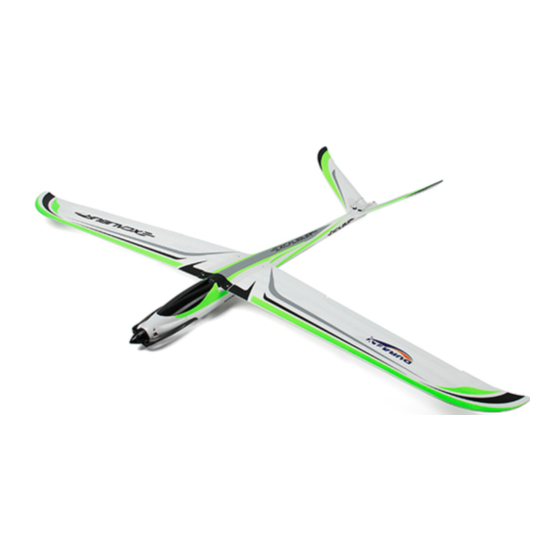
INSTRUCTIONS FOR ZEPHYR V-70 EDF-EPO
Warning: This aircraft is a hobby grade product, only for people of 14 years of
age or above.
Please read and understand all instructions before opeating.
Features:
1)This product features the updated aerodynamic design, fulfilling a perfect c
ombination with installation of EDF , which is therefore considered as the hig
h-speed glider plane.
2) Bilateral air intakes allows for reliable ventilation,keep the edf perfect blend
in the side of body.
3) The 70mm EDF providing the enormous power is perfect for the plane being
either flying or guiding.
4) Ultrathin aerofoil design, ensure the high speed in flying and combine
performan of glider.
5) Enjoying the top speed around 140km/h.
Product Specifications
Fuselage length: 1000mm ( 39.4 in.)
Wingspan: 1533mm ( 60.4 in.)
Flying Weight: 1050-1150g ( with battery )
Power: 70mm edf
Motor:2223 3400KV Brushless Outrunner
ESC: 55 Amp
Servo: 9g*4 micro servo
Radio:4/more channel
Receiver:4/more channel
Advertisement

Related Manuals for Durafly ZEPHYR V-70 EDF-EPO


Summary of Contents for Durafly ZEPHYR V-70 EDF-EPO
- Page 1 INSTRUCTIONS FOR ZEPHYR V-70 EDF-EPO Warning: This aircraft is a hobby grade product, only for people of 14 years of age or above. Please read and understand all instructions before opeating. Features: 1)This product features the updated aerodynamic design, fulfilling a perfect c ombination with installation of EDF , which is therefore considered as the hig h-speed glider plane.
- Page 2 Battery: 11.1V 2800-3500mah lipo 25c Motor Spes: Motor: 2223 KV:3400 Technical Datas 3400 Configuration 9N6P Stator Diameter 22mm STator Length 23mm Shaft Diameter Φ28×40m Motor Dimension(Dia.﹡Len) Weight(g) ldle current(10)@10v(A) No.of Cells(Lipo) 3S-4S Max Continuous current(A)180S Max Continuous 750W Power(W)180S Max. efficiency current >82% internal resistance 248mΩ...
- Page 3 1.Applying the decals All the adhesive labels and decals are prepared and installed at factory. If it is not the case, follow the above illustrations applying the labels and/or the decals to your plane by yourself. Foam parts included in the packing: 1 Fuselage 2 Left wing 3 Right wing...
- Page 4 7 Canopy 1pc 8 Right servo arm protector 1pc 9 Left servo arm protector 1pc 10 Screw for EDF cover 1pc 11 Mounting screws for EDF cover 4pcs 12 Glass fiber stick for linking the wing 13 Steel wire for push-and- pull of the wing 2pcs 14 Steel wire for push-and-pull of the spoiler type 1 15 Steel wire for push-and-pull of the spoiler type 2 16 Mounting screws for the wing 2pcs...
- Page 5 3) Connect right and left wing by using the grass fibre stick as shown in the picture Aiming holes, insert pins. 5) Install the main wing to the bottom of the fuselage by using the mountin g screws and pads provided. 6) Install the EDF in place onto the fuselage with 4pcs of mounting screws as...
- Page 6 shown in the picture. Note: Keep all wires in order during installation and never get them installed reverse. 7) Place the cover of EDF and fasten it with due care by using the mounting screws. 8) Following the illustrations install the servos seperately to both right and left aileron , secure with the thrust steel wire , and then stick the cover onto the ar Note: Tuck the connecting wires of the servos into the slots.
- Page 7 9) Install the rear rudder servo as shown in the picture. ( Replace with the long er connecting wires if necessary.) 10) Install the servo arm and the thrust steel wire as shown in the picture , level up the rear rudder and centre it in place.
- Page 8 11 Install receiver, ESC and battery, and power on, then debug before fly. 12 After test, you can cover the equipment cabin canopy as picture shown. Recommended Flying Setup Max servo travel of aileron: 25 degrees up and 25degrees down(20mm) Max servo travel of elevator:15 degrees up and 15 degrees down(15mm)...
- Page 9 Setting the Centre of Gravity Like any other aircraft, it must be balanced at a particular point in order to achieve stable flying characteristics. Assemble your model ready to fly, and install the flight battery. The Centre of Gravity (CG) should be at a position of 84 mm away from wing leading edge, please refer to attached picture.
Need help?
Do you have a question about the ZEPHYR V-70 EDF-EPO and is the answer not in the manual?
Questions and answers