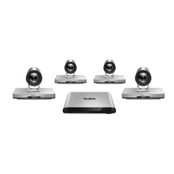
Yealink VC880 Administrator's Manual
Full hd video conferencing system
Hide thumbs
Also See for VC880:
- Administrator's manual (217 pages) ,
- User manual (104 pages) ,
- Quick start manual (20 pages)
Table of Contents
Advertisement
Advertisement
Table of Contents

Related Manuals for Yealink VC880


Summary of Contents for Yealink VC880
-
Page 2: Table Of Contents
Hardware of VCR11 Remote Control....................... 27 Hardware of VCM34..............................29 Hardware of MSpeaker............................30 LED Instructions..................................31 LED Instructions of VC880/VC800/VC500/VC200/PVT980/PVT950............. 31 Power Indicator LED of VP59..........................31 Camera Indicator LED of VP59........................... 32 LED Instructions of VCC22 Video Conferencing Camera................. 32 LED Instructions of CTP20............................ - Page 3 | Contents | iii Customizing the Key Type............................40 Disabling Remote Control Keys..........................41 Disabling the Remote Control..........................41 Using CTP20 Touch Panel..............................41 Using CP960 Conference Phone............................42 Device Type Licenses and Multipoint Licenses......... 42 Licenses....................................... 42 Multipoint Licenses................................42 Importing Device Type License/Multipoint License....................43 Traditional Deployment Methods..............
- Page 4 Configuring H.323 Accounts..........................82 H.323 Tunneling................................ 85 Configuring the PSTN account............................86 Configuring the Video Conference Platform Account.................... 86 Registering a Yealink Cloud Account.......................87 Registering a YMS Account..........................89 Registering a StarLeaf Account.......................... 91 Logging into Zoom Cloud Platform......................... 92 Registering a Pexip Account..........................93 Logging into the BlueJeans Cloud Platform....................
- Page 5 | Contents | v Hiding the Time and the Date on the Status Bar..................113 Hiding the User Interface on Idle Screen....................114 Showing or Hiding Icons in a Call........................114 Muting the Microphone..............................118 Configuring Microphone Mute Mode.........................118 Configuring the Keyboard Input Method........................119 Configuring USB Storage..............................119 Configuring Local Storage...............................
- Page 6 | Contents | vi Selecting Video Frame Rate and Resolution......................147 Configuring the Monitor Resolution..........................147 Configuring VC200 Experimental Access (Auto Framing)................... 148 Configuring Content Sharing..............149 Configuring Dual-Stream Protocol..........................149 Configuring the H.239 Protocol........................150 Configuring BFCP (Binary Floor Control dual Protocol).................150 Configuring Mix-Sending..............................151 Configure Content Sharing..............................151 Configuring Camera Settings..............152 Selecting and Setting Cameras............................
- Page 7 Local Directory..................................184 Adding Local Contacts and Conference Contacts..................184 Importing a Local Contact List......................... 186 Exporting Local Contact List..........................187 Editing Local Contacts............................188 Deleting Local Contacts............................188 Yealink Cloud Contacts..............................189 Enterprise Directory................................189 LDAP......................................190 LDAP Attributes...............................190 Configuring LDAP..............................191 Meeting Whitelist.................................193 Adding Meeting Whitelist..........................194 Deleting the Meeting Whitelist........................194...
- Page 8 | Contents | viii Supported Cipher Suites............................. 202 TLS Transport Protocol............................203 Managing the Trusted Certificates List......................204 Managing the Server Certificates........................206 Secure Real-Time Transport Protocol (SRTP)..................... 207 H.235....................................209 Defending against Attacks..........................210 System Integrated with Control Systems........................211 Connection Methods of Control Systems....................212 Connection Settings for Control Systems....................212 CEC Monitor Controls................
- Page 9 | Contents | ix Upgrading the Firmware............................. 230 Viewing Multipoint License Status..........................231 Viewing the Device Type..............................232 Troubleshooting..................232 General Issues..................................232 Call Issues....................................233 Audio Issues................................... 235 Video Issues....................................236 Placing a Test Call................................237 System Diagnostics................................237 Diagnosing the Audio............................238 Diagnosing the Camera............................238 Diagnosing the Network.............................238 System Status..................................
-
Page 10: About This Guide
• Yealink CP960 HD IP Conference Phone Quick Reference Guide, which describes how to use CP960 conference phone. • Yealink Wi-Fi USB Dongle WF50 User Guide, which describes how to connect the wireless network to the VCS codec and provide wireless AP via WF50. -
Page 11: Getting Started
• Yealink WPP20 Wireless Presentation Pod Quick Start Guide, which describes how to connect WPP20 wireless presentation pod to the VCS codec. • Yealink PSTN Box CPN10 Quick Start Guide, which describes how to connect VCS codec to PSTN. • Yealink VCC22 Video Conferencing Camera Quick Start Guide, which describes how to connect the VCC22 video conferencing cameras to VCS codec. - Page 12 | Getting Started | 12 Port Name Description ① LED Indicator Indicate different status of the system. ② Reset Key Reset the system to factory defaults. ③ • Connect to a USB flash drive. Insert a USB flash drive for storing screenshots, recording videos or capturing packets.
-
Page 13: Hardware Of Pvt980 Codec
| Getting Started | 13 Hardware of PVT980 Codec PVT980, targeted at large meeting room, is applicable to the meeting room with a rack or the lecture hall. Possessing rich physical interfaces for audio and video connection, PVT980 can be connected to the 3rd- party camera or access to the video matrix. -
Page 14: Hardware Of Vc800 Codec
• Rear Panel of VC800 Codec Front Panel of VC800 Codec The LED indicator in front of the camera indicates different camera statuseses. Related information LED Instructions of VC880/VC800/VC500/VC200/PVT980/PVT950 Rear Panel of VC800 Codec Port Name Description ① Line Out Connect to an audio output device via an audio cable (3.5mm). -
Page 15: Hardware Of Vc500/Pvt950 Codec
| Getting Started | 15 Port Name Description ③ • Connect to a USB flash drive. Insert a USB flash drive for storing screen shots, the recorded videos and captured packets. If multiple USB flash drives are connected, only the last one can be identified. - Page 16 • Front Panel of VC500/PVT950 Codec • Rear Panel of VC500 Codec Front Panel of VC500/PVT950 Codec The LED indicator in front of the camera indicates different camera statuseses. Related information LED Instructions of VC880/VC800/VC500/VC200/PVT980/PVT950 Rear Panel of VC500 Codec...
-
Page 17: Hardware Of Vc200 Codec
Hardware of VC200 Codec Yealink VC200 is an entry-level smart video conferencing endpoint designed for small and huddle room. VC200 possesses many features, including ultra HD 4K, 4 x digital zoom camera, 103° super-wide angle lens, white balance automatic gain and others. With 6 beamforming microphone arrays for direct voice pickup and Yealink Noise Proof Technology, VC200 brings excellent audio effect in small rooms and ensures that everyone can be heard clearly. - Page 18 | Getting Started | 18 Front Panel of VC200 Codec The LED indicator in front of the camera indicates different camera statuses. Related information LED Instructions of VC880/VC800/VC500/VC200/PVT980/PVT950 Rear Panel of VC200 Codec Port Name Description ① • Connect to a USB flash drive for storing screen shots, the recorded videos and captured packets.
-
Page 19: Hardware Of Vp59 Codec
| Getting Started | 19 Bottom of VC200 Codec Port Name Description ⑦ VESA Fix VC200 to the TV stand or a tripod via a 1/4”-20 UNC screw. ⑧ Reset Key Reset the system to factory defaults. Hardware of VP59 Codec You can use VP59 as a video phone on your desktop, you can also use it as a video conferencing device in a small meeting room of 20-30 square meters. - Page 20 | Getting Started | 20 Name Description Power Indicator Indicates the call status and the system status. Touch Screen Touch to select the desired item. Displays the time, the date, the call and other related information. MESSAGE Key Not available. HEADSET Key Toggles and indicates the headset mode.
-
Page 21: Hardware Of Vcc22 Video Conferencing Camera
Connect to a USB flash drive/WPP20/CPN10/USB to Line output. Hardware of VCC22 Video Conferencing Camera VCC22 is a video conferencing camera for VC880/VC800/PVT980. It adopts 12x optical zoom lens, supports 1080P/60 frame full HD video, has OSMO and PTZ function, and possesses professional video quality and environmental adaptability. -
Page 22: Hardware Of Vch50 Video Conferencing Hub
| Getting Started | 22 Related information LED Instructions of VCC22 Video Conferencing Camera Rear Panel of VCC22 Video Conferencing Camera Port Name Description ① HDMI Out Connect to a monitor for displaying shared content. ② Camera Port Connect to a PoE switch. ③... - Page 23 | Getting Started | 23 Left Side of VCH50 Cable Hub Port Name Description ① Codec Connect to the video conferencing system via the provided 7.5m network cable. Right Side of VCH50 Cable Hub Port Name Description ② Audio Connect to the CP960 Conference phone via the provided 0.5m network cable.
-
Page 24: Hardware Of Cp960 Conference Phone
Hardware of CP960 Conference Phone You can use CP960 conference phone as a microphone and a speaker when you are using VC200/VC500/ VC800/VC880/PVT980/PVT950 to place calls. You can also place calls, answer calls or view directory and history on the CP960 conference phone. -
Page 25: Introduction Of Ctp20 Touch Panel
As the controller of VCS devices, CTP20 touch panel can help you fully control VC200/VC500/VC800/ VC880/PVT980/PVT950 system. You can use it to place calls, initiate conferences, adjust the volume, control the camera, record videos, and so on. What’s more, CTP20 supports collaborative editing and the annotation feature, that is to say, participants can add notes to the presentation or to the whiteboard, which can improve the communication efficiency of the traditional video conferencing presentation. -
Page 26: Hardware Of Cpe90 Wired Expansion Microphones
| Getting Started | 26 Name Description ① Connects to the video conferencing system to obtain Wi-Fi profile. Connects to the PC for sharing content. ② Presentation Button Press it to start or to stop sharing the full screen of the PC. Long press it for 3 seconds and release it, and then choose the window you want to share. -
Page 27: Hardware Of Cpw90-Bt Bluetooth Wireless Microphone
| Getting Started | 27 Name Description ① Built-in Microphones Supports 360-degree audio pickup at a radius of up to 3 meters. ② Mute Button • Indicates call status. • Toggles mute feature. Related information Mute Indicator LED of CPE90 Wired Expansion Microphones Hardware of CPW90-BT Bluetooth Wireless Microphone The CPW90-BT is a Bluetooth wireless microphone, which can work as the audio input device of the video conferencing system. - Page 28 | Getting Started | 28 Name Description Power Key • Power on or power off the system. • Put the system to sleep or wake up the system. Video Recording Key Start or stop recording the video and audio. Layout Key Adjust the layout during a video call.
-
Page 29: Hardware Of Vcm34
| Getting Started | 29 Name Description Volume down key Decrease the speaker volume. Zoom in key • Increase the focal length of the camera. • Zoom in the screenshot. • Turn the page up. Zoom out key • Decrease the focal length of the camera. •... -
Page 30: Hardware Of Mspeaker
| Getting Started | 30 Rear Panel of VCM34 Name Description ① It is used to connect VCM34 to the VC Hub/Phone port on the video conferencing system. ② Internet It is used to connect VCM34. Hardware of MSpeaker Front Panel of MSpeaker... -
Page 31: Led Instructions
It is used to connect MSpeaker to VC800 Line Out Port as an audio input. LED Instructions You can know the system status by viewing the LED light. • LED Instructions of VC880/VC800/VC500/VC200/PVT980/PVT950 • Power Indicator LED of VP59 • Camera Indicator LED of VP59 •... -
Page 32: Camera Indicator Led Of Vp59
The VC880/VC800/PVT980 system is powered on. The VC880/VC800/PVT980 is upgrading firmware. The VCC22 video conferencing camera is working. Solid red The VC880/VC800/PVT980 system is in sleep mode. The VCC22 video conferencing camera is disabled. Flashing red The VCC22 video conferencing camera is upgrading firmware. -
Page 33: Led Instructions Of Ctp20
| Getting Started | 33 LED Instructions of CTP20 LED Status Description Solid green VCS codec is powered on. Solid red CTP20 is in sleep mode. Solid orange CTP20 is not connected to VCS codec. Mute Indicator LED of CP960 Conference Phone LED Status Description Solid red... -
Page 34: Led Instructions Of Wpp20 Wireless Presentation Pod
The WPP20 cannot find or connect to the video conferencing system in 10 seconds after start-up. The WPP20 pairs to the video conferencing system successfully, but it does not detect that the Yealink Wireless Presentation Pod software is running on your PC. Yealink Wireless Presentation Pod software is turned off. -
Page 35: Powering On And Off
| Getting Started | 35 LED Status Description Firmware update fails. Wi-Fi profile update fails. Powering on and off • Powering on VC880/VC800/VC500/VC200/PVT980/PVT950 • Powering off VC880/VC800/VC500/VC200/PVT980/PVT950 • Powering on or Powering off VP59 • Initialization Process Overview Powering on VC880/VC800/VC500/VC200/PVT980/PVT950 Your system starts up automatically after you connect an electrical supply. -
Page 36: Running The Setup Wizard
(Only applicable to VC200/ VP59) Identity Optional: Log into the video conferencing platform. Your system supports Yealink VC Cloud/Yealink Meeting Server/StarLeaf/ Zoom/Pexip/BlueJeans/EasyMeet/Videxio/Custom platform. Configuration Methods To configure your system, you can use the remote control, CTP20, CP960, or the web user interface. -
Page 37: Using Web User Interface
• On your web user interface, go to Network > Advanced > Web Server. • On your VCS: On your VC880/VC800/VC500/PVT980/PVT950, go to More > Setting > Advanced > Advanced Network > Web Server Type. On your VC200, go to More > Network > Wired Network > Advanced Network > Web Server Type. -
Page 38: User And Administrator Account Login
| Configuration Methods | 38 2. Configure and save the following settings: Parameter Description Configuration Method HTTP Enable or disable the user to access the web Web user interface user interface via the HTTP. Endpoint Default: On. CTP20 HTTP Port Web user interface Specify the HTTP port for the user to access the web user interface. - Page 39 | Configuration Methods | 39 Configuring an Administrator Password The default administrator name is “admin” and the administrator password is “0000”. Only the user with the administrator permission can change the password. For security reasons, you should change them as soon as possible.
-
Page 40: Using Vcr11 Remote Control
| Configuration Methods | 40 Parameter Description Configuration Method User Password (New Password Web user interface Configure a user password. and Confirm Password) Note: the system supports ASCII characters 32-126 (0x20-0x7E). You can also leave the password blank. Using VCR11 Remote Control You can use the real remote control or the virtual remote control to configure and use the system. -
Page 41: Disabling Remote Control Keys
Using CTP20 Touch Panel You can use CTP20 Touch Panel to configure and control VC880/VC800/VC500/VC200. For more information about how to use CTP20 Touch Panel, refer to Yealink CTP20 Quick Start Guide. -
Page 42: Using Cp960 Conference Phone
You can get the device type license from Yealink technical support. After changing to a normal machine, the system supports 1 video call and 5 voice calls (1 conference organizer and 6 participants). -
Page 43: Importing Device Type License/Multipoint License
| Traditional Deployment Methods | 43 Multipoint License Type Maximum Connections Description VC880/VC800 with a trial 24-way video call with a Period of validity: 15-day free multipoint license presentation (a conference trial. moderator and 24 participants) VC880/VC800 share this trial multipoint license. -
Page 44: Public Ip Configuration
| Traditional Deployment Methods | 44 Public IP Configuration If you have a high expectation for the audio and video quality, you can connect your video conferencing system to the Internet directly. This deployment method involves a simple setup process but creates a stable network environment. However, it is more expensive due to leased line costs. -
Page 45: Configuring Nat
• On your web user interface, go to Network > NAT/Firewall > NAT Configuration. • On your VCS: On your VC880/VC800/VC500/PVT980/PVT950, go to More > Setting > Advanced > NAT/Firewall > NAT. On your VC200, go to More > Network > Wired Network > NAT/Firewall > NAT. -
Page 46: Enabling Static Nat Feature For Sip Protocol(Sip Account And Sip Ip Call)
• On your web user interface, go to Network > NAT/Firewall > NAT Configuration. • On your VCS: On your VC880/VC800/VC500/PVT980/PVT950, go to More > Setting > Advanced > NAT/Firewall > NAT. On your VC200, go to More > Network > Wired Network > NAT/Firewall > NAT. -
Page 47: Stun
| Traditional Deployment Methods | 47 2. Configure and save the following settings: Parameter Description Configuration Method Static NAT/Type Select Manual/Manual Web user interface Settings, and then configure the Endpoint NAT address manually. CTP20 NAT Public IP Address/Public Configure the NAT address for Web user interface IP Address the system manually. -
Page 48: Configuring Stun
• On your web user interface, go to Network > NAT/Firewall > STUN Config. • On your VCS: On your VC880/VC800/VC500/PVT980/PVT950, go to More > Setting > Advanced > NAT/Firewall > STUN Config. On your VC200, go to More > Network > Wired Network > NAT/Firewall > STUN Config. -
Page 49: Enabling Stun Feature For Sip Protocol
| Traditional Deployment Methods | 49 Parameter Description Configuration Method STUN Port Configure the port of the STUN Web user interface (Simple Traversal of UDP over Endpoint NATs) server. CTP20 Default: 3478. Enabling STUN Feature for SIP Protocol If you want to make private-to-public calls via SIP protocol (SIP account and SIP IP call), you can enable STUN feature for SIP protocol. -
Page 50: Configuring H.460 For H.323 Protocol
| Traditional Deployment Methods | 50 If you configure H.323 settings and enable H.460, the system ignores the static NAT settings automatically. • Configuring H.460 for H.323 Protocol Configuring H.460 for H.323 Protocol If you want to make private-to-public calls via H.323 protocol, you can enable H.460 feature for H.323 protocol. -
Page 51: Configuring Data Intelligent Traversal
| Traditional Deployment Methods | 51 The VCS A locates in the intranet with the feature of audio & video intelligent traversal enabled, and the router does not support the ALG feature. The VCS B locates in the public network. A calls B, and then A sends the RTP packets to the B. -
Page 52: Vpn
• On your web user interface, go to Network > Advanced > VPN. • On your VCS: On your VC880/VC800/VC500/PVT980/PVT950, go to More > Setting > Advanced > Advanced Network > VPN . On your VC200, go to More > Network > Wired Network > Advanced Network > VPN. -
Page 53: Cloud Deployment Method
| Cloud Deployment Method | 53 2. Configure and save the following settings: Parameter Description Configuration Method Active/ Enable or disable VPN feature on Web user interface the system. Endpoint Note: the default value is Off. CTP20 If you change this parameter, the system will reboot to make the change take effect. -
Page 54: Configuring Ipv4 Or Ipv6
| Configuring Network Settings | 54 Configuring IPv4 or IPv6 Yealink video conferencing system supports IPv4 addressing mode, IPv6 addressing mode, as well as the IPv4&IPv6 dual stack-addressing mode. Note: Yealink video conferencing systems comply with the DHCPv4 specifications documented in 2131, and the DHCPv6 specifications documented in 3315. - Page 55 • On your web user interface, go to Network > LAN Configuration > IPv4 Config. • On your VCS: On your VC880/VC800/VC500/PVT980/PVT950, go to More > Setting > Advanced > Wired Network > IPv4. On your VC200, go to More > Network > Wired Network > IPv4.
-
Page 56: Configuring Ipv6
| Configuring Network Settings | 56 Parameter Description Configuration Method Gateway/ Configure the gateway assigned Web user interface to the system. Default Gateway Endpoint Note: It is configurable only CTP20 when the network type is selected as Static IP. If you change this parameter, the system will reboot to make the change take effect. - Page 57 • On your web user interface, go to Network > LAN ConfigurationIPv6 Config. • On your VCS: On your VC880/VC800/VC500/PVT980/PVT950, go to More > Setting > Advanced > Wired Network > IPv6. On your VC200, go to More > Network > Wired Network > IPv6.
-
Page 58: Wi-Fi
Wi-Fi For VC880/VC800/VC500/PVT980/PVT950, you need to connect a WF50 Wi-Fi USB Dongle to the system for connecting to the wireless network. You can connect the VC200/VP59 to the wireless network directly. •... - Page 59 1. Do one of the following: • On your VCS: On your VC880/VC800/VC500/PVT980/PVT950, go to More > Setting > Advanced > Wi-Fi. On your VC200, go to More > Network > Wi-Fi. On your VP59, tap Setting > Network & Connection > Wi-Fi.
-
Page 60: Viewing The Wireless Network Status
• On your web user interface, go to Network > Wi-Fi > Wi-Fi Status. • On your VCS: On your VC880/VC800/VC500/PVT980/PVT950, go to More > Setting > Advanced > Wi-Fi > Wi-Fi Status. On your VC200, go to More > Network > Wi-Fi > Wireless Status. -
Page 61: Wireless Access Point
| Configuring Network Settings | 61 Wireless Access Point For VC880/VC800/VC500/PVT980/PVT950, you need to connect a WF50 Wi-Fi USB Dongle to the system for providing the wireless AP. VC200/VP59 can provide wireless AP directly. • Enabling the Wireless Access Point •... - Page 62 | Configuring Network Settings | 62 2. Configure and save the following settings: Parameter Description Configuration Method AP Name Configure the name of wireless Web user interface Endpoint CTP20 Security Mode Configure the security mode of Web user interface the wireless AP. Endpoint •...
-
Page 63: Viewing The Connected Devices
1. Do one of the following: • On your VCS: On your VC880/VC800/VC500/PVT980/PVT950, go to More > Setting > Advanced > Wireless AP > AP Device List. On your VC200, go to More > Network > Wireless AP > AP device list. -
Page 64: Removing Devices From The Blacklist
Procedure 1. Do one of the following: • On your VCS: On your VC880/VC800/VC500/PVT980/PVT950, go to More > Setting > Advanced > Wireless AP > Blacklist. On your VC200, go to More > Network > Wireless AP > Blacklist. On your VP59, tap Setting > Network & Connection > Wireless AP > Blacklist. -
Page 65: Dhcp Options
For more information on DHCP options, refer to RFC 2131 2132. • Supported DHCP Option of IPv4 • DHCP Option 42, Option 2 • DHCP Option 12 Supported DHCP Option of IPv4 The following table lists the DHCP options supported by Yealink VCS in IPv4 network. -
Page 66: Dhcp Option 42, Option 2
| Configuring Network Settings | 66 Parameter DHCP Options Description Subnet Mask Specify the subnet mask of the client. Time Offset Specify the offset between the client subnet and the Coordinated Universal Time (UTC). Router Specify a list of IP addresses for routers on the client’s subnet. -
Page 67: Vlan
In addition to manual configuration, the system also supports automatic discovery of VLAN via LLDP or DHCP. The assignment takes effect in this order: assignment via LLDP, manual configuration, then assignment via DHCP. For more information on VLAN, refer to VLAN Feature on Yealink IP Phones. • Configuring LLDP •... -
Page 68: Configuring Vlan Manually
• On your web user interface, go to Network > Advanced > LLDP. • On your VCS: On your VC880/VC800/VC500/PVT980/PVT950, go to More > Setting > Advanced > Advanced Network > LLDP. On your VC200, go to More > Network > Wired Network > Advanced Network > LLDP. -
Page 69: Configuring Dhcp Vlan
| Configuring Network Settings | 69 2. Configure and save the following settings: Parameter Description Configuration Method Active Enable or disable VLAN for the Web user interface Internet port. Endpoint Note: the default value is Off. CTP20 If you change this parameter, the system will reboot to make the change take effect. -
Page 70: 802.1X Authentication
• On your web user interface, go to Network > Advanced > 802.1x. • On your VCS: On your VC880/VC800/VC500/PVT980/PVT950, go to More > Setting > Advanced > Advanced Network > 802.1x Mode. On your VC200, go to More > Network > Wired Network > Advanced Network > 802.1 Mode. - Page 71 | Configuring Network Settings | 71 2. Configure and save the following settings: Parameter Description Configuration Method 802.1x Mode Specify the 802.1x authentication Web user interface mode. Endpoint • Disabled CTP20 • EAP-MD5 • EAP-TLS • PEAP-MSCHAPv2 • EAP-TTLS/EAP-MSCHAPv2 Note: the default value is disabled.
-
Page 72: Network Speed And Duplex Mode
Supported Transmission Methods • Configuring Transmission Methods Supported Transmission Methods The supported transmission methods for VC880/VC800/VC500/PVT980/PVT950 system’s Internet port are listed below: • Auto • Full Duplex (transmit in 10Mbps, 100Mbps or 1000Mbps) • Half Duplex (transmit in 10Mbps or 100Mbps) The supported transmission methods for VC200 endpoint’s Internet port are listed below:... -
Page 73: Restricting Reserved Ports
• On your web user interface, go to Network > NAT/Firewall > Reserved Port. • On your VCS: On your VC880/VC800/VC500/PVT980/PVT950, go to More > Setting > Advanced > NAT/Firewall > Reserved Port. On your VC200, go to More > Network > Wired Network > NAT/Firewall > Reserved Port. -
Page 74: Quality Of Service (Qos)
• On your web user interface, go to Network > Advanced > QoS. • On your VCS: On your VC880/VC800/VC500/PVT980/PVT950, go to More > Setting > Advanced > Advanced Network > QoS. On your VC200, go to More > Network > Wired Network > Advanced Network > QoS. -
Page 75: Configuring Mtu
| Configuring Network Settings | 75 2. Configure and save the following settings: Parameter Description Configuration Method QoS Enable Enable or disable the QoS Web user interface feature. Endpoint Note: the default value is Off. CTP20 If you change this parameter, the system will reboot to make the change take effect. - Page 76 • On your web user interface, go to Network > Advanced > MTU. • On your VCS: On your VC880/VC800/VC500/PVT980/PVT950, tap MoreSetting > Advanced > Advanced Network > Network MTU (1000-1500). On your VC200, go to More > Network > Wired Network > Advanced Network > Network MTU (1000-1500).
-
Page 77: Configuring Account Settings
Logging out of the Video Conference Platform Setting SIP Account/SIP IP Call Yealink video conferencing system supports Session Initiation Protocol (SIP). If your server supports SIP, you can make a voice/video call using the SIP account or IP address. •... - Page 78 | Configuring Account Settings | 78 Parameter Description Configuration Method Password The registration password of this Web user interface SIP account. Endpoint Note: the default value is blank. CTP20 Server Host/Server The IP address or domain name Web user interface of the SIP server.
- Page 79 | Configuring Account Settings | 79 Parameter Description Configuration Method Transport Specify the transport protocol Web user interface for transmitting the SIP Endpoint signaling. CTP20 The supported protocols are as follows: • UDP—it provides the best transmission for SIP signaling. •...
-
Page 80: Configuring Sip Ip Call
You can use the SIP protocol for SIP IP call, which means dialing the IP address of the other party instead of the account. If you do not want the third-party or Yealink old devices (for example, VC110/VC120/ VC400/T49G or VC800/VC500/VC200 running firmware version 40 or earlier) to make IP calls to you, you can enable the advanced security feature and set the IP call password. - Page 81 Default: On. If advanced security is enabled and the IP call password is configured, the third-party or Yealink old devices need to use “password@IP” to call in for the SIP IP call. IP Call Password (is not Configure the password for the...
-
Page 82: Setting H. 323 Account/H.323 Ip Call
| Configuring Account Settings | 82 Setting H. 323 Account/H.323 IP Call The H.323 protocol is enabled by default. You can place IP calls via the H.323 protocol. If your network uses a gatekeeper, you can register an H.323 account for the system, and specify its H.323 name and extension. This allows others to call you via your H.323 name or the extension instead of the IP address. - Page 83 | Configuring Account Settings | 83 Parameter Description Configuration Method H.323 Extension Configure the device extension Web user interface that can be identified by the Endpoint gatekeepers and gateways. CTP20 Note: the default value is blank. If two devices are registered to the same gatekeeper, they can make point-to-point calls by dialing their extensions.
- Page 84 | Configuring Account Settings | 84 Parameter Description Configuration Method Port/Gatekeeper Port 2 Configure the port for the Web user interface secondary gatekeeper. Endpoint Note: the default port number CTP20 is 1719. The value can be any integer from 0 to 65535. Gatekeeper Authentication/ Enable or disable support for the Web user interface...
-
Page 85: H.323 Tunneling
| Configuring Account Settings | 85 Parameter Description Configuration Method Local Early Media Web user interface Enable or disable the local early media feature on the device. • Off—the local system sends an Open Logical Channel (OLC) message and receives the acknowledgement message of OLC from the far site. -
Page 86: Configuring The Pstn Account
• Custom Note: If you purchase the VC200 Custom Edition for Yealink Cloud, your endpoint can register a Yealink Cloud account only. Other Cloud platforms are unavailable on your endpoint. What’s more, you cannot register a SIP account or H.323 account, and cannot dial an IP address. -
Page 87: Registering A Yealink Cloud Account
Administrator Guide. The terminal supports using the user name and password to log in to the Yealink cloud account. The VP59 phone also supports using the Pin code to log in to the Yealink cloud account. When you log into the Yealink VC Cloud Management Service, you can: •... - Page 88 Yealink VC Cloud Management Service platform. • PIN Code Login: This method uses the user’s PIN code to log into the Yealink VC Cloud Management Service platform. The 9-digit PIN code is disposable and expires if it is unused for 7 days.
-
Page 89: Registering A Yms Account
Service via Username/password can this feature be configured. Note: A Yealink Cloud account can be logged into 5 devices at most simultaneously. Registering a YMS Account You can use Yealink YMS account to log into Yealink Meeting Server (YMS). About this task... - Page 90 Note: A YMS account can be logged into 5 devices at most simultaneously. If the enterprise administrator enables the Device upgrade feature on Yealink Meeting Server, video conferencing systems with YMS accounts logged into will upgrade the firmware automatically once they receive the new firmware from Yealink Meeting Server.
-
Page 91: Registering A Starleaf Account
| Configuring Account Settings | 91 Registering a StarLeaf Account You can log into the StarLeaf Cloud platform. About this task When you place a call using the StarLeaf Cloud account, you can: • Call the other StarLeaf Cloud account to establish a point to point call. •... -
Page 92: Logging Into Zoom Cloud Platform
| Configuring Account Settings | 92 Logging into Zoom Cloud Platform You can log into Zoom cloud platform and call into the permanent VMRs to join the video conferences with other participants. Procedure 1. Do one of the following: • On your web user interface, go to Account > VC Platform. •... -
Page 93: Registering A Pexip Account
| Configuring Account Settings | 93 Parameter Description Configuration Method Server Expires Web user interface The registration timeout (in seconds) of the device. After the timeout, the device will send the registration request to the server again. Default: 3600 seconds. Keep Alive Interval Web user interface Configure the interval (in... - Page 94 | Configuring Account Settings | 94 Parameter Description Configuration Method Alias Specify the alias when Web user interface registering a Pexip account. Endpoint Note: the default value is blank. CTP20 Username Specify the username for this Web user interface Pexip account. Endpoint Note: the default value is blank.
-
Page 95: Logging Into The Bluejeans Cloud Platform
Default: 30 seconds. Note: Yealink VCS also allows you to register a Pexip account via the standard H.323 or SIP protocol. For more information, refer to Setting SIP Account/SIP IP Call Setting H. 323 Account/H.323... - Page 96 | Configuring Account Settings | 96 Procedure 1. Do one of the following: • On your web user interface, go to Account > VC Platform. • On your VCS, go to More > Setting > Advanced > Video Conference Platform. On your VP59, go to Setting >...
-
Page 97: Registering An Easymeet Account
| Configuring Account Settings | 97 Parameter Description Configuration Method Server Expires Web user interface The registration timeout (in seconds) of the device. After the timeout, the device will send the registration request to the server again. Default: 3600 seconds. Keep Alive Interval Web user interface Configure the interval (in... - Page 98 | Configuring Account Settings | 98 Parameter Description Configuration Method Username Specify the username for this Web user interface EasyMeet account. Endpoint Note: the default value is blank. CTP20 Password Specify the password for this Web user interface EasyMeet account. Endpoint Note: the default value is blank.
-
Page 99: Logging Into Videxio Platform
| Configuring Account Settings | 99 Parameter Description Configuration Method Server Expires Web user interface The registration timeout (in seconds) of the device. After the timeout, the device will send the registration request to the server again. Default: 3600 seconds. Keep Alive Interval Web user interface Configure the interval (in... -
Page 100: Registering A Custom Account
| Configuring Account Settings | 100 Registering a Custom Account You can register a custom account for communication. Procedure 1. Do one of the following: • On your web user interface, go to Account > VC Platform. • On your VCS, go to More > Setting > Advanced > Video Conference Platform. On your VP59, go to Setting >... - Page 101 | Configuring Account Settings | 101 Parameter Description Configuration Method Port Configure the port of the custom Web user interface server. Endpoint Note: the default port number is CTP20 0. The value can be any integer from 0 to 65535. Remember password Enable or disable the system to Endpoint...
-
Page 102: Logging Out Of The Video Conference Platform
| Configuring Basic Settings | 102 Logging out of the Video Conference Platform Procedure 1. Do one of the following: • On your web user interface, go to Account > VC Platform > Log Out. • On your VCS, go to More > Setting > Advanced > Video Conference Platform > Log out. On your VP59, tap Setting >... -
Page 103: Setting The Language
| Configuring Basic Settings | 103 2. Configure and save the following settings: Parameter Description Configuration Method Sitename Icon Configure the site name of the Web user interface system. Endpoint Note: you can enter 64 CTP20 characters at most. Setting the Language You can specify a language displayed in the monitor and the web user interface respectively. -
Page 104: Time Zone
| Configuring Basic Settings | 104 • Setting the Time Reminder Time Zone You can set the time difference between GMT (Greenwich Mean Time) and your location. Therefore, different areas can keep the time consistent for the commence and communication. The following table lists the available time zone on video conferencing system. - Page 105 | Configuring Basic Settings | 105 Time Zone Time Zone Name Time Zone Time Zone Name -04:30 Venezuela (Caracas) +04:00 Azerbaijan (Baku) -04:00 Canada (Halifax, Saint +04:00 Georgia (Tbilisi) John) -04:00 Chile (Santiago) +04:00 Kazakhstan (Aktau) -04:00 Paraguay (Asuncion) +04:00 Russia (Samara) -04:00 United Kingdom-...
-
Page 106: Ntp Settings
| Configuring Basic Settings | 106 Time Zone Time Zone Name Time Zone Time Zone Name +01:00 Chad +10:00 Australia (Brisbane) +01:00 Spain (Madrid) +10:00 Australia (Hobart) +01:00 Croatia (Zagreb) +10:00 Russia (Vladivostok) +01:00 Czech Republic (Prague) +10:30 Australia (Lord Howe Islands) +01:00 Denmark (Kopenhagen) -
Page 107: Configuring The Dst
| Configuring Basic Settings | 107 Parameter Description Configuration Method DHCP Time Web user interface Enable or disable the system to update time with the offset time offered by the DHCP server. Note: the default value is Off. It is only available when the time zone is GMT 0. - Page 108 | Configuring Basic Settings | 108 2. Configure and save the following settings: Parameter Description Configuration Method Daylight Saving Time Configure the type of DST. Web user interface The available types for the Endpoint system are as below: CTP20 • Disabled: do not use DST. •...
-
Page 109: Manually Configuring The Time And Date
| Configuring Basic Settings | 109 Parameter Description Configuration Method DST Start Month Web user interface When you select By Week as the fixed type, configures the start DST Start Day of Week time of DST. DST Start Day of Week Last in Note: It only works when you Month enable Daylight Saving Time. -
Page 110: Customizing The Time And Date Format
| Configuring Basic Settings | 110 Customizing the Time and Date Format You can customize the time and date by choosing among a variety of time and date formats. Procedure 1. Do one of the following: • On your web user interface, go to Setting > Date&Time. •... -
Page 111: Enabling/Disabling The Clock For The Vp59
• On your web user interface, go to Setting > General > General Information > Automatic Sleep Time. • For your VC880/VC800/VC500/VC200/PVT980/PVT950, on your remote control, go to More > Setting > Call Feature > Automatic Sleep Time. • On your CTP20, tap Setting > Basic > Automatic Sleep Time. -
Page 112: Allowing Website Snapshot
| Configuring Basic Settings | 112 2. Configure and save the following settings: Parameter Description Configuration Method Automatic Sleep Time Configure the inactive time Web user interface (minutes) before the system Endpoint enters sleep mode. CTP20 Note: the default value is 10 minutes. -
Page 113: Customizing The Local Interface For The System
| Configuring Basic Settings | 113 2. Configure and save the following settings: Parameter Description Configuration Method Screen Saver Wait Time Configure the inactive time Web user interface (minutes) after which the system Endpoint starts the screen saver. CTP20 Default: 1 minute. Customizing the Local Interface for the System You can configure the time after which the system starts screen saver, and customize the screen to show or hide some information. -
Page 114: Hiding The User Interface On Idle Screen
| Configuring Basic Settings | 114 2. Configure and save the following settings: Parameter Description Configuration Method Hide Heading Time Web user interface Enables the monitor to hide the time and the date on the status bar. • On—do not display the heading time. - Page 115 | Configuring Basic Settings | 115 2. Configure and save the following settings: Parameter Description Configuration Method Title Bar Web user interface Enable or disable the system to hide the title bar during a call. • Show- the system displays the title bar.
- Page 116 | Configuring Basic Settings | 116 Parameter Description Configuration Method Camera Icon Web user interface Enable or disable the system to hide the camera icon ( during a call. • Show- the system displays the camera icon. • Hide with UI- the system displays the camera icon and then hide it after five seconds.
- Page 117 | Configuring Basic Settings | 117 Parameter Description Configuration Method Hold Icon Web user interface Enable or disable the system to hide the hold icon ( ) during a call. • Show- the system displays the hold icon. • Hide with UI- the system displays the hold icon and then hide it after five seconds.
-
Page 118: Muting The Microphone
• On your web user interface, go to Home > Mute. • On your VCS: For VC880/VC800/VC500/VC200/PVT980/PVT950, on your remote control, press On your VP59, press the MUTE key on the phone. • On your CP960, tap one of the Mute keys. -
Page 119: Configuring The Keyboard Input Method
| Configuring Basic Settings | 119 2. Configure and save the following settings: Parameter Description Configuration Method Microphone Mute Mode Web user interface Configure the microphone mute mode. • Synchronized- if you mute/ unmute a microphone, other microphones will be muted/ unmuted simultaneously. -
Page 120: Configuring Local Storage
| Configuring Basic Settings | 120 2. Configure and save the following settings: Parameter Description Configuration Method USB Enable Web user interface Enable or disable the USB feature. Note: the default value is On. If you change this parameter, the system will reboot to make the change take effect. -
Page 121: Taking Screenshots
| Configuring Basic Settings | 121 2. Configure and save the following settings: Parameter Description Configuration Method Screenshot Web user interface Enable or disable to capture the screenshot by using the remote control. • On • Off Default: On. • Taking Screenshots Related tasks Configuring USB Storage... - Page 122 Web user interface Confirm action on the system manually when you use WPP20 to record. Default: On. It is only applicable to VC200/ VC500/VC800/VC880/VP59. Dual Screen Web user interface Select the desired screen. You can record the Recording Setting video on the selected screen when you are using dual screen.
-
Page 123: Basic Settings For The Cp960 Conference Phone
| Configuring the Audio Settings | 123 Basic Settings for the CP960 Conference Phone The screen saver automatically starts when the system or CP960 conference phone has been idle for the preset waiting time. You can set screen saver for the monitor and CP960 conference phone respectively. •... -
Page 124: Configuring The Audio Output
Audio Output Type Model Audio Output VC880/VC800/VC200/PVT980 • Auto- selects the audio output with the highest priority. If the audio output with the highest priority is removed, the system will select the device with the second highest priority. The priority is VCS Phone>HDMI>Line Output. -
Page 125: Specifying An Available Audio Output
• On your web user interface, go to Setting > Video & Audio > Audio Settings. • On your VCS: On your VC880/VC800/VC500/PVT980/PVT950, go to More > Setting > Video & Audio > Audio Settings. On your VC200, go to More > Setting > Video & Audio. -
Page 126: Audio Input
Audio Input Type • Specifying an Available Audio Input Audio Input Type Model Audio Input VC880/VC800/PVT980 • Auto—the system automatically selects the audio input with the highest priority. The priority is VCS Phone>Bluetooth Microphone>Line Input. • VCS Phone • Bluetooth Microphone •... -
Page 127: Specifying An Available Audio Input
• On your web user interface, go to Setting > Video & Audio > Audio Settings. • On your VCS: On your VC880/VC800/VC500/PVT980/PVT950, go to More > Setting > Video & Audio > Audio Settings. On your VC200, go to More > Setting > Video & Audio. - Page 128 | Configuring the Audio Settings | 128 Parameter Description Configuration Method Line AEC Web user interface Enable or disable echo cancellation for line input device. • On- eliminate the echo to the line input devices. If you select an acoustic device (for example: a microphone) to be the line input, you can enable this configuration.
-
Page 129: Media Audio Input
• On your web user interface, go to Setting > Video & Audio > Audio Settings. • On your VCS: On your VC880/VC800/VC500/PVT980/PVT950, go to More > Setting > Video & Audio > Audio Settings. On your VC200, go to More > Setting > Video & Audio. -
Page 130: Configuring The Eq Self-Adaption
• The VCS phone is not selected as the audio output device. • Connect an audio input to the device (it is only applicable to VC880/VC800/ VC500/PVT980/PVT950) • The audio output is HDMI or Line Output/USB Line out. Configuring the Noise Suppression The noises in the room may be picked-up, including paper rustling, coffee mugs, coughing, typing and silverware striking plates. -
Page 131: Tones
| Configuring the Audio Settings | 131 Procedure 1. On your web user interface, go to Setting > Video & Audio > Noise Suppression. 2. Configure and save the following settings: Parameter Description Configuration Method Temporal Noise Shaping(TNS) Web user interface Enables or disabled the Transient Noise Suppressor (TNS). -
Page 132: Custom Tones Formats
| Configuring the Audio Settings | 132 Custom Tones Formats You can customize different tones for the system except for the default tone. The custom tones formats are as below: E1,E2,E3,E4,E5,E6,E7,E8 (you can configure up to 8 different tones which are separated by commas) En=[!][F1][+F2][+F3][+F4] /Duration Parameter explanation: •... -
Page 133: Codecs
| Configuring the Audio Settings | 133 Codecs CODEC is an abbreviation of COmpress-DECompress, and is capable of coding or decoding a digital data stream or signal by implementing an algorithm. The object of the algorithm is to represent the high-fidelity audio/video signal with a minimum number of bits while retaining quality. -
Page 134: Video Codecs
• Off—keep the current codec byte sequence. • On—different devices have different definition about audio codec byte sequence, which may lead to the audio incompatibility problems between Yealink and certain devices. You can enable this feature to solve these incompatibility problems. Default: Disabled. Video Codecs The video codecs that the system uses to establish a call should be supported by the server. - Page 135 | Configuring the Audio Settings | 135 • Supported Video Codecs • Configuring Video Codecs • Selecting an H.265 Mode Supported Video Codecs The following table summarizes the supported video codecs on the system: Video Codecs Static NAT/Type Bit Rate Frame Frame Size Rate...
-
Page 136: Dtmf
| Configuring the Audio Settings | 136 Selecting an H.265 Mode You can select VBR or CBR for the H.265 video codec according to your network bandwidth. It is only applicable to VC200 endpoint. Procedure 1. On your web user interface, go to Account > Codec > Video Codec. 2. -
Page 137: Transmission Ways Of Dtmf
| Configuring the Audio Settings | 137 Transmission Ways of DTMF Three ways to transmit DTMF tones are as below: RFC2833, INBAND, SIP INFO. RFC 2833 In-band transmission method. DTMF tones are transmitted by RTP, and the RFC 2833 packets are marked by TeleponeEvent (RTP PayloadType). -
Page 138: Configuring Dtmf For H.323 Protocol
| Configuring Video Settings | 138 Parameter Description Configuration Method DTMF Info Type Configure the DTMF info type when DTMF Web user interface type is set to SIP INFO or RFC2833+SIP Endpoint INFO. CTP20 • DTMF-Relay • DTMF • Telephone-Event Default: DTMF-Relay. -
Page 139: Display Layout Settings
| Configuring Video Settings | 139 Display Layout Settings • Setting the Default Layout for a Single Screen • Configuring Change Layout by Content Sharing • Hiding Local Video Image in Equal Layout • Configuring Hide Local Video When PIP •... -
Page 140: Configuring Change Layout By Content Sharing
| Configuring Video Settings | 140 Configuring Change Layout by Content Sharing The Change Layout by Content Sharing is enabled by default. When you are making a presentation on the PC, the layout of the image displayed in the device (except for VP59) is changed into 1+N or voice- activated mode automatically, and the content is enlarged and displayed in the screen. -
Page 141: Configuring Multi-Camera Default Layout
| Configuring Video Settings | 141 2. Configure and save the following settings: Parameter Description Configuration Method Hide Local Video When PIP Web user interface Enable or disable the local video image to hide in the PIP (Picture- in-Picture). • On—the local video image is hidden in the PIP. -
Page 142: Configuring Voice Activation
The active speaker is fixed at the bottom-left corner, and other video images will be switched automatically. Note: The view switching is only applicable to VC880/VC800/PVT980/PVT950 system with a multipoint license. It is not applicable to VC500/VC200 endpoint. •... - Page 143 | Configuring Video Settings | 143 • Configuring 1+N Mode Configuring the Average Mode In Equal N×N layout, when the number of participants exceeds 9, all participants’ video images will be switched automatically. You can configure the switching mode. Procedure 1.
-
Page 144: Configuring Preview Local
| Configuring Video Settings | 144 Parameter Description Configuration Method Full Screen Round Switches all video images Web user interface (except for the active speaker and the content) at a time. Configuring Preview Local If there is no local screen in the current layout (such as remote full screen or split mode does not display local), the local thumbnail image cannot be viewed when adjusting the local camera, so the camera cannot be accurately adjusted. -
Page 145: Configuring Hdmi Extended Display By Vp59
| Configuring Video Settings | 145 Configuring HDMI Extended Display by VP59 After you enable the HDMI feature on VP59, if you connect a monitor to the phone during a video call, the video images of the remote party and the shared content are displayed on the monitor, and the call control page is displayed on phone screen. -
Page 146: Maximizing Monitor Video Display
Output For Display 2 Web user interface Specify the content to be displayed on the secondary monitor. • Auto—The secondary monitor displays the content in this priority: PC>VC880/VC800/ VC500/PVT980/PVT950 Camera>Camera N. • PC—The secondary monitor displays the PC content. • VC880/VC800/VC500/ PVT980/PVT950 Camera—The... -
Page 147: Selecting Video Frame Rate And Resolution
| Configuring Video Settings | 147 Selecting Video Frame Rate and Resolution To transfer a clear and smooth video, you can specify the maximum frame and resolution for local video according to the network environment. Procedure 1. On your web user interface, go to Setting > Video & Audio > Main. 2. -
Page 148: Configuring Vc200 Experimental Access (Auto Framing)
• The number of face detections on the VC200 can support up to 8 faces simultaneously in a range of 5 meters. • The experimental access is a new feature that Yealink is still researching and developing. It is available to users for trial use in advance, but this feature is still unstable now. It is not... -
Page 149: Configuring Content Sharing
The Yealink video conferencing system supports the standard H.239 protocol and BFCP (Binary Floor Control Protocol). The Yealink Cloud account and YMS account support dual-stream protocol by default. If you want to share contents during the call using the SIP protocol and H.323 protocol, you need to enable the H.239 protocol and BFCP in advance. -
Page 150: Configuring The H.239 Protocol
Enable or disable the BFCP. Note: For Zoom/Pexip/BlueJeans/ EasyMeet/Videxio/Custom and SIP IP call, BFCP is enabled by default. For SIP account, BFCP is disabled by default. This feature is not applicable to Yealink StarLeaf Cloud platform. Related tasks Configuring Mix-Sending... -
Page 151: Configuring Mix-Sending
| Configuring Content Sharing | 151 Configuring Mix-Sending During a call, the device of the remote party may not support dual-stream protocol. Therefore, you need enable this feature, so that multiple video streams (the local video + the local content) can be synthesized to one video stream and sent to the remote. -
Page 152: Configuring Camera Settings
Web user interface resolution when the content is sharing. • 1080P • 720P Default: 1080P. Configuring Camera Settings You can configure the following settings on VC880/VC800/VC500/VC200/PVT980/PVT950. • Selecting and Setting Cameras • Viewing Camera Status • Adjusting Camera Angle and Focus •... -
Page 153: Viewing Camera Status
| Configuring Camera Settings | 153 2. Configure and save the following settings: Parameter Description Configuration Method Camera Configure the desired camera. Web user interface Status Enable or disable the selected camera. Web user interface Default: On. It is not applicable to VC200/VC500/PVT950. Select a Camera Web user interface Customize the camera name. -
Page 154: Adjusting Camera Angle And Focus
• On your web user interface, go to Setting > Camera > White Balance. • On your VCS: On your VC880/VC800/VC500/PVT980/PVT950, go to More > Setting > Camera Setting > White Balance Mode. On your VC200, go to More > Setting > Video & Audio > White Balance Mode. -
Page 155: Adjusting The Exposure
Configuration Method White Balance Mode Configure the white balance Web user interface mode of the camera. Endpoint • Auto—Yealink recommends CTP20 that you use this setting for most situations. It calculates the best white balance setting based on lighting conditions in the room. -
Page 156: Configuring Auto Exposure Mode
• On your web user interface, go to Setting > Camera > Exposure. • On your VCS: On your VC880/VC800/VC500/PVT980/PVT950, go to More > Setting > Camera > Exposure. On your VC200, go to More > Setting > Video & Audio > Exposure. -
Page 157: Configuring Manual Exposure Mode
• On your web user interface, go to Setting > Camera > Exposure. • On your VCS: On your VC880/VC800/VC500/PVT980/PVT950, go to More > Setting > Camera > Exposure. On your VC200, go to More > Setting > Video & Audio > Exposure. -
Page 158: Configuring The Mode Of Shutter Priority
• On your web user interface, go to Setting > Camera > Exposure. • On your VCS: On your VC880/VC800/VC500/PVT980/PVT950, go to More > Setting > Camera > Exposure. On your VC200, go to More > Setting > Video & Audio > Exposure. -
Page 159: Configuring Aperture Priority
• On your web user interface, go to Setting > Camera > Exposure. • On your VCS: On your VC880/VC800/VC500/PVT980/PVT950, go to More > Setting > Camera > Exposure. On your VC200, go to More > Setting > Video & Audio > Exposure. - Page 160 | Configuring Camera Settings | 160 2. Select Aperture Priority from the Exposure Mode drop-down menu. 3. Configure and save the following settings: Parameter Description Configuration Method Aperture Disable aperture or set the desired value. Web user interface Value: F1.6, F2.0, F2.4, F2.8, F3.4, Endpoint F4.0, F4.8, F5.6, F6.8, F8, F9.6, CTP20...
-
Page 161: Configuring The Mode Of Brightness Priority
• On your web user interface, go to Setting > Camera > Exposure. • On your VCS: On your VC880/VC800/VC500/PVT980/PVT950, go to More > Setting > Camera > Exposure. On your VC200, go to More > Setting > Video & Audio > Exposure. -
Page 162: Configuring The Mode Of Wdr-Auto
1. Do one of the following: • On your web user interface, go to Setting > Camera > Exposure. • On your VC880/VC800/VC500/PVT980/PVT950, go to More > Setting > Camera > Exposure. • On your CTP20, tap Setting > Camera > Exposure. -
Page 163: Configuring Wdr-Manual
1. Do one of the following: • On your web user interface, go to Setting > Camera > Exposure. • On your VC880/VC800/VC500/PVT980/PVT950, go to More > Setting > Camera > Exposure. • On your CTP20, tap Setting > Camera > Exposure. - Page 164 | Configuring Camera Settings | 164 2. Configure and save the following settings: Parameter Description Configuration Method Display Mode Configure the display mode of Web user interface the camera. Endpoint • High Definition CTP20 • Standard • Mild • Custom Default: Standard.
-
Page 165: Adjusting Hangup Mode And Camera Pan Direction
• On your web user interface, go to Setting > Camera > Other Settings. • On your VCS: On your VC880/VC800/VC500/PVT980/PVT950, go to More > Setting > Camera Setting > Graphics. On your VC200, go to More > Setting > Video & Audio > Graphics. -
Page 166: Configuring Continuous Auto Focus
1. Do one of the following: • On your web user interface, go to Setting > Camera > Focus. • For VC880/VC800/VC500, go to More > Setting > Camera Setting. • On your CTP20, tap Setting > Camera. 2. Configure and save the following settings:... -
Page 167: Setting The Camera Presets
You can add, modify, and delete the preset. Note: For more information about configuring presets via CP960 conference phone, CTP20 or the remote control, refer to the Yealink Full HD Video Conferencing System User Guide. Allowing the Remote System to Control Your Camera You can allow the far site to control your camera, so that the far-end can meet their watching need. - Page 168 | Configuring Camera Settings | 168 Configuring FECC (H.323) Protocol When logging in to the StarLeaf platform or using an H.323 account, you can enable the FECC (H.323) protocol for H.323 calls. To control the far-site camera, both parties should enable this protocol simultaneously.
-
Page 169: Configuring The Far Site To Control The Near Camera
3. Confirm the action. Configuring the Meeting Room Yealink video conferencing system can act as a virtual meeting room, so that other devices can dial the system to join a meeting. Your system supports the following two conference types: regular mode conference room and virtual meeting room. -
Page 170: Conference Types
For PVT950, up to joins the meeting. 4 video calls and 5 voice calls. VMR Mode VC800/VC880 with a multipoint Virtual meeting The total MCU ways of license room 1: when the two virtual meeting participants call... -
Page 171: Vmr Mode Conference
In VMR mode conference, MCU can be used to host two independent conferences, corresponding to virtual meeting room 1 and virtual meeting room 2. This feature is only applicable to VC800/VC880/PVT980. You cannot use the VMR mode conference when multiple cameras are connected. -
Page 172: Configuring Meeting Password
| Configuring the Meeting Room | 172 3. Configure and save the following settings: Parameter Description Configuration Method Multipoint AllocationVirtual Allocates the maximum ways of Web user interface Meeting Room 1 video calls for virtual meeting room 1. Multipoint AllocationVirtual Allocates the maximum ways of Web user interface Meeting Room 2... -
Page 173: Joining The Vmr
About this task If you do not register a Cloud account, or you only register a Yealink Cloud account or YMS account, you can configure a third-party VMR (StarLeaf/Zoom/BlueJeans/Pexip/EasyMeet/Videxio Platform) in advance, so that you can quickly join a VMR without registering a third-party Cloud account. -
Page 174: Configuring Call Settings
• The VMR name 3 to 5 is empty by default. It only works when you do not log into a Cloud platform, or you only register a Yealink Cloud account/YMS account. VMR Server 1 to 5 Web user interface The IP address or the domain name of the VMR server. -
Page 175: Selecting A Call Protocol
| Configuring Call Settings | 175 • Auto Answer • Muting Auto-Answered Calls • Muting Auto-Dialed Calls • DND (Do Not Disturb) • Enabling Fast Audio Call for CP960 Conference Phone Selecting a Call Protocol The system supports SIP and H.323 protocols for the incoming and the outgoing calls. Procedure 1. -
Page 176: Account Polling
Example 1. System A is registered with a Yealink Cloud account and a SIP account. 2. Select the call type automatically. Dial the number. • If account polling is enabled, system A will use its Cloud account (highest priority) to call system B first. -
Page 177: Configuring Additional Audio Call
| Configuring Call Settings | 177 2. Configure and save the following settings: Parameter Description Configuration Method Account Polling Web user interface Enable or disable the account polling on the system. • Off—the system dials a number by using the call type with the highest priority. - Page 178 P2P call. Endpoint own capacity to initiate a conference call VC880/VC800 system (without an imported multipoint license) uses Cloud account or YMS account to make a P2P call. VC880/VC800 system (with an...
-
Page 179: Configuring Call Match
Procedure 1. Do one of the following: • On your web user interface, go to Setting > Call Features. • For your VC880/VC800/VC500/VC200/PVT980/PVT950, go to More > Setting > Call Feature. 2. Configure and save the following settings: Parameter Description... -
Page 180: Configuring Sip Ip Call By Proxy
| Configuring Call Settings | 180 7. The list shown on the top has the highest priority. The system will search the list with higher priority preferentially. Configuring SIP IP Call by Proxy If the account of far site is an URI address (for example, 8000@XX.com), you can use SIP IP address or SIP account to call the far site. -
Page 181: Configuring The Auto Refuse Timeout
| Configuring Call Settings | 181 Configuring the Auto Refuse Timeout The auto refuse timeout defines a specific period of time after which the system will stop ringing if the call is not answered. Procedure 1. On your web user interface, go to Setting > Call Features. 2. -
Page 182: Answering Multiple Calls Automatically
1. Do one of the following: • On your web user interface, go to Setting > Call Features. • For your VC880/VC800/VC500/VC200/PVT980/PVT950, on your remote control user, go to More > Setting > Call Feature. • On your CP960, swipe down from the top of the screen to enter the control center. -
Page 183: Dnd (Do Not Disturb)
Do one of the following during a call: • On your web user interface, go to Home > DND. • On your VCS: For VC880/VC800/VC500/VC200/PVT980/PVT950, on your remote control, press or OK key to open Talk Menu, and then select DND. -
Page 184: Enabling Fast Audio Call For Cp960 Conference Phone
1. On your web user interface, go to Setting > Call Features. 2. Enable Fast Audio Call. Managing the Directory This chapter describes how to manage and configure directory settings. Your system provides local directory, Yealink cloud directory, Yealink enterprise directory and LDAP directory. • Local Directory •... - Page 185 For more information, refer to Specifying the Video Call Rate Adding Conference Contacts You can add 100 conference contacts at most. About this task Note: Adding Conference contact is only applicable to VC880/VC800/PVT980/PVT950 system with a multipoint license. It is not applicable to VC500/VC200/VP59.
-
Page 186: Importing A Local Contact List
The number of local contacts that you can add to a conference contact depends on the imported multipoint license. For example, if you import a 24-way license to your VC880/VC800, up to 24 local contacts can be added to a conference contact. For more information the MCU certificate, contact the system administrator. -
Page 187: Exporting Local Contact List
| Managing the Directory | 187 Parameter Description Configuration Method Delete Old Contacts Web user interface It will delete all existing local contacts while importing the contact list. • Check—delete the old contacts. • Uncheck—do not delete the old contacts. Ignore This column will not be imported Web user interface... -
Page 188: Editing Local Contacts
| Managing the Directory | 188 Editing Local Contacts Procedure 1. Do one of the following: • On your web user interface, go to Directory > Local Directory. Hover your cursor over the desired local contact, and click • On your VCS, go to Dial > Directory. Select the desired contact and then press the right key. -
Page 189: Yealink Cloud Contacts
YMS contacts which are created and managed by your enterprise administrator. Note that only the enterprise administrator can add, edit and delete YMS contacts on the Yealink Meeting Server. On your system, you can only search for and place calls to the YMS contacts. -
Page 190: Ldap
| Managing the Directory | 190 • VMR: it is also called the permanent VMR. The enterprise administrator can determine whether to synchronize the permanent VMR to your system or not. Related tasks Registering a YMS Account LDAP LDAP is an application protocol for accessing and maintaining information services for the distributed directory over an IP network. -
Page 191: Configuring Ldap
| Managing the Directory | 191 Abbreviation Name Description ipPhone IPphoneNumber The home phone number Configuring LDAP Procedure 1. On your web user interface, go to Directory > LDAP. 2. Configure and save the following settings: Parameter Description Configuration Method LDAP Enable Web user interface Enable or disable the LDAP... - Page 192 LDAP server. LDAP Base Web user interface Configure the root path of the LDAP search base. Example: cn=manager,dc=yealink,dc=cn Max.Hits Web user interface Configure the maximum number of search results returned by the LDAP server. Valid Value: 1 to 32000, default value: 50.
-
Page 193: Meeting Whitelist
| Managing the Directory | 193 Parameter Description Configuration Method LDAP Display Name Web user interface Configure the contact attributes displayed on the LCD screen. Note: multiple contact attributes should be separated by spaces. Example: %cn Protocol Web user interface Specify the protocol for the LDAP server. -
Page 194: Adding Meeting Whitelist
| Managing the Directory | 194 Adding Meeting Whitelist The users in the whitelist can call you without the password. Procedure 1. On your web user interface, go to Directory > Meeting Whitelist. 2. Enter the desired number. The value can be the IP address, the account number, or the domain name. 3. -
Page 195: Managing The Call Log
1. Do one of the following: • On your web user interface, go to Setting > Call Features. • For your VC880/VC800/VC500/VC200/PVT980/PVT950, go to More > Setting > Call Feature. 2. Enable or Disable History Record. Adding a History Record to the Local Directory Procedure 1. -
Page 196: Deleting A History Record
| Managing the Call Log | 196 • Deleting Multiple History Records • Deleting All History Records Deleting a History Record Procedure 1. Do one of the following: • On your VCS, go to Dial > History. Select the desired entry and then press the right navigation key to select Delete. On your VP59, select the desired history record, tap beside the desired entry, and tap in the... -
Page 197: Placing Calls From Call History
| Placing a Call | 197 Placing Calls from Call History Procedure Do one of the following: • On your web user interface, go to Directory > History. Click beside the desired entry to place a video or audio call. •... -
Page 198: Placing A Call From The Search Result
| Placing a Call | 198 • On your web user interface, go to Home. Enter the number in the Enter Number field. Select the desired call type and video call rate. Click Video Call or Voice Call to place a video or voice call. •... -
Page 199: Placing A Call From The Search Result By Ctp20
| Placing a Call | 199 Placing a Call from the Search Result by CTP20 Procedure 1. On your CTP20, tap Dial. 2. Optional: In the bottom-right corner, tap Auto and select the desired call type from the drop-down menu. 3. -
Page 200: Configuring The Security Features
| Configuring the Security Features | 200 Configuring the Security Features The following introduces how to configure the security features. • Collaboration Data Security Control • Configuring the Auto Logout Time • Transport Layer Security (TLS) • System Integrated with Control Systems Collaboration Data Security Control By default, the authentication is required for the WPP20 and CTP20 via wireless connection when receiving shared content or initiating receiving whiteboard. -
Page 201: Configuring The Auto Logout Time
| Configuring the Security Features | 201 Parameter Description Configuration Method Verify Status Cache Time In Web user interface Configure the cached Idle authentication status time of the WPP20/CTP20 when not in a call. Note: It is configurable only when the accessories join collaboration confirmation feature is enabled. -
Page 202: Supported Cipher Suites
| Configuring the Security Features | 202 • Secure Real-Time Transport Protocol (SRTP) • H.235 • Defending against Attacks Supported Cipher Suites The system supports TLS version 1.0, 1.1 and 1.2. A cipher suite is a named combination of authentication, encryption, and message authentication code (MAC) algorithms used to negotiate the security settings for a network connection by using the TLS/SSL network protocol. -
Page 203: Tls Transport Protocol
DNS NAPTR and SRV request to find the service type and the port if no server port is given. Note: • Yealink Cloud Platform and StarLeaf Cloud platform cannot be configured. • The default value of the Zoom/Pexip/BlueJeans/ Videxio/Custom Cloud platform is TCP. -
Page 204: Managing The Trusted Certificates List
| Configuring the Security Features | 204 Managing the Trusted Certificates List When the system serves as a TLS client and requests a TLS connection with a server, the system should verify the server certificate sent by the server to decide whether it is trusted based on the trusted certificates list. - Page 205 • Default Certificates List Default Certificates List The following introduces 36 most common used CA Certificates built in Yealink video conferencing system. • VeriSign Class 3 Public Primary Certification Authority - G5 • GeoTrust Universal CA • Equifax Secure eBusiness CA-1 •...
-
Page 206: Managing The Server Certificates
• Class 4 Public Primary Certification Authority - G2 Note: The most common used CA Certificates are built in Yealink phones. Due to memory constraints, we cannot ensure a complete set of certificates. If there is no desired certificate in the above list, contact your distributor for the desired one. -
Page 207: Secure Real-Time Transport Protocol (Srtp)
| Configuring the Security Features | 207 2. Configure and save the following settings: Parameter Description Configuration Method Device Certificates Web user interface Specify the type of the server certificates for the system to send for TLS authentication. • Default Certificates •... - Page 208 | Configuring the Security Features | 208 m=audio 11780 RTP/SAVP 0 8 18 9 101 a=crypto:1 AES_CM_128_HMAC_SHA1_80 inline:NzFlNTUwZDk2OGVlOTc3YzNkYTkwZWVkMTM1YWFj a=crypto:2 AES_CM_128_HMAC_SHA1_32 inline:NzkyM2FjNzQ2ZDgxYjg0MzQwMGVmMGUxMzdmNWFm a=crypto:3 F8_128_HMAC_SHA1_80 inline:NDliMWIzZGE1ZTAwZjA5ZGFhNjQ5YmEANTMzYzA0 a=rtpmap:0 PCMU/8000 a=rtpmap:8 PCMA/8000 a=rtpmap:18 G729/8000 a=fmtp:18 annexb=no a=rtpmap:9 G722/8000 a=fmtp:101 0-15 a=rtpmap:101 telephone-event/8000 a=ptime:20 a=sendrecv The callee receives the INVITE message with the RTP encryption algorithm, and then answers the call by replying the 200 OK message which carries the negotiated RTP encryption algorithm.
- Page 209 | Configuring the Security Features | 209 2. Configure and save the following settings: Parameter Description Configuration Method SRTP Web user interface Specify the SRTP type. The supported types are as follows: • Disabled—the encrypted calls are not supported. • Optional—both encrypted and unencrypted calls are supported.
-
Page 210: Defending Against Attacks
| Configuring the Security Features | 210 2. Configure and save the following settings: Parameter Description Configuration Method H.235 Web user interface Configure the H.235 encryption. The supported types are as follows: • Disabled—the encrypted calls are not supported. • Optional—both the encrypted and the unencrypted calls are supported. -
Page 211: System Integrated With Control Systems
Default: Disabled. System Integrated with Control Systems Yealink video conferencing system provides API for third-party control system to integrate with. Therefore, third-party control system can control Yealink video conferencing system via API. This feature is not applicable to VP59. -
Page 212: Connection Methods Of Control Systems
• LAN Connection: Make sure the Yealink video conferencing system and the control system are in the same network segment. If you use this mode to control the system, TCP protocol is recommended. To establish a connection, the control system needs to know the IP address and TCP port of the Yealink video conferencing system. - Page 213 • 9600 • 19200 • 38400 • 115200 Default: 115200 Note: The baud rate must be same between the control system and Yealink video conferencing system. Data Bits Web user interface Configure the data bits. • 7 • 8 Default: 8...
-
Page 214: Cec Monitor Controls
HDMI by using only one remote control. The users can use a remote control to control all the devices connected by HDMI. The CEC feature is enabled by default on VC880/VC800/VC500/PVT980/PVT950 video conferencing system. Ensure that all monitors connected to the system supports and enables the CEC feature. This feature is not applicable to VC200/VP59. -
Page 215: Accessories With Your System
Using VCM34 Using the VCC22 Video Conferencing Cameras You can connect up to 9 VCC22 video conferencing cameras to the VC880/PVT980 video conferencing system. For VC800 video conferencing system, you can connect up to 8 VCC22 video conferencing cameras. For more information, refer to Yealink VCC22 Camera Quick Start Guide. -
Page 216: Adjusting The Camera Layout During A Call
| Accessories with Your System | 216 3. Configure and save the following settings: Parameter Description Configuration Method Multi-camera Default Layout/ Configure the camera layout Web user interface Camera Layout during a video call. Endpoint • 1+N: the selected camera CP960 Conference Phone is given prominence in the largest pane, and other... -
Page 217: Using The Cpw90-Bt Bluetooth Wireless Microphones With Vcs
Just turn the Bluetooth wireless microphones on to use them. If the model of your video conferencing system is VC500/VC800/VC880/PVT980/PVT950, make sure a BT42 Bluetooth USB Dongle is connected before you use the Bluetooth wireless microphones. If you purchase Bluetooth wireless microphones separately, you need to pair them with video conferencing system manually. -
Page 218: Viewing The Information Of Bluetooth Wireless Microphones
The mute indicator LED on the CPW90-BT flashes red and green alternately. Using CTP20 The CTP20 supports wired and wireless connections. The PVT980/PVT950/VC880/VC800/VC500 can connect up to 4 CTP20s and the VC200 supports only one CTP20. VP59 cannot be used with a CTP20. -
Page 219: Using Multiple Ctp20S For Collaboration
Using Multiple CTP20s for Collaboration In a meeting room, you can use multiple CTP20s for whiteboard collaboration or presentation. Up to 4 CTP20s can be connected to the PVT980/PVT950/VC880/VC800/VC500 codec simultaneously and up to 1 CTP20 can be connected to the VC200 codec. -
Page 220: Using Vcm34
| System Maintenance | 220 Procedure 1. In the note toolbar, tap > Save/Share. 2. Do one of the following: • Tap Save to cloud disk to save the whiteboard to the YMS server. • Tap Send E-mail, enter the email address and then tap Send to share whiteboard via email. Multiple email addresses are separated by commas (half-width, full-width) or semicolons (half-width, full-width). -
Page 221: Importing Bin Files To The System
| System Maintenance | 221 2. Click Export. Importing BIN Files to the System Procedure 1. On your web user interface, go to Setting > Configuration > Configuration > Import Configuration. 2. Click Browse and select a BIN configuration file from your computer. 3. -
Page 222: Resetting The System Via Configuration Methods
| System Maintenance | 222 Resetting the System via Configuration Methods Procedure 1. Do one of the following: • On your web user interface, go to Setting > Upgrade > Reset to Factory Setting. • On your VCS, go to More > Setting > Advanced > Reboot & Reset > Reset. On your VP59, Setting >... -
Page 223: Setting The Severity Level Of The Local Log
| System Maintenance | 223 • Exporting the Log Files to a USB Flash Drive • Exporting the Log Files to a Syslog Server Setting the Severity Level of the Local log Procedure 1. On your web user interface, go to Setting > Configuration > Local Log. 2. -
Page 224: Exporting The Log Files To A Local Pc
| System Maintenance | 224 2. Configure and save the following settings: Parameter Description Configuration Method Module Log Level Web user interface Specify the module log level. • All—all modules • Driver • System • Service • Connectivity • Video & Audio •... -
Page 225: Exporting The Log Files To A Usb Flash Drive
3. In the USB Auto Exporting Syslog field, select On. 4. Click Confirm. A folder named yealink.debug appears in your USB flash drive, which includes the log files. Note: The severity level of the exported Module Log will not be greater than the local Log Level. For example: If you set Local Log Level to 3 and set Talk log Level to 6, the exported Talk log Level will still be 3. -
Page 226: Capturing Packets
| System Maintenance | 226 Parameter Description Configuration Method Syslog Level Web user interface Specify the level of syslog information that displayed in the syslog. 0-system is unusable 1-action must be taken immediately 2-critical condition 3-error conditions 4-warning conditions 5-normal but significant condition 6-informational Note: the default value is 6. - Page 227 | System Maintenance | 227 • Capturing the Packets in Normal Way Capturing the Packets in Enhanced Way You can capture more packets in enhanced way than in normal mode. Procedure 1. On your web user interface, go to Setting > Configuration. 2.
- Page 228 | System Maintenance | 228 Parameter Description Configuration Method Pcap Filter Type Web user interface Configure the filter type of the packet to capture. The supported types are as follows: • Custom—Customize the packet filter string. • SIP or H245 or H225— Capture SIP, H245 and H225 packets.
-
Page 229: Capturing The Packets Via Remote Control
Connect the Internet ports of your system and your computer to the same HUB, and then use Ethernet software to capture the signal traffic. System Firmware The new features may be added to the newly released firmware. Therefore, Yealink recommends you to update your devices to the latest firmware. -
Page 230: Upgrading The Firmware
Device model Firmware Name Example VP59 video conferencing system 91.x.x.x.rom 91.332.0.15.rom VC200 video conferencing system 80.x.x.x.rom 80.41.0.20.rom VC880 video conferencing system 63.x.x.x.rom 63.41.0.20.rom VC800 video conferencing system VC500 video conferencing system VCC22 Video Conferencing Camera PVT980 video conferencing 1345.x.x.x.rom 1345.41.0.20.rom... -
Page 231: Viewing Multipoint License Status
| System Maintenance | 231 Viewing Multipoint License Status Procedure 1. Do one of the following: • On your web user interface, go to Security > License. • On your VCS, go to More > Status > License. • On your CP960 conference phone, go to Settings > License. •... -
Page 232: Viewing The Device Type
| Troubleshooting | 232 Viewing the Device Type You can view the device type, whether it is a demo machine or a normal machine. For VP59, there are no different device types. Procedure Do one of the following: • On your web user interface, go to Security > License. •... -
Page 233: Call Issues
| Troubleshooting | 233 Symptom Reason Solution You may control the far-site Ensure that you are controlling camera during a call. the near-site camera. There are some objects Ensure that no objects are obstructing the sensor in front of obstructing the sensor in front of the camera. - Page 234 | Troubleshooting | 234 Situation Reason Solution The account is not registered Check whether the call parties register the accounts. Fail to dial the IP address of the At least one call protocol(SIP/ far site. H.323) is enabled. Ping the IP address of the far site.
-
Page 235: Audio Issues
| Troubleshooting | 235 Audio Issues Symptom Reason Solution You cannot hear the audio during The volume is set to 0. Adjust the volume. a call. The far site mutes the Contact the far site to check microphone. whether the microphone is unmuted. -
Page 236: Video Issues
| Troubleshooting | 236 Video Issues Symptom Reason Solution No picture on the monitor. The system is in sleep mode. Press any key on the remote control to wake up the system. The system is powered off. The system is powered on. The HDMI cable is not connected Make sure that the monitor is to the system. -
Page 237: Placing A Test Call
When you finish installing and deploying the video conferencing system, you can call the Yealink Demo site (117.28.251.50 or 117.28.234.45) to test your system. If you fail to establish a call with Yealink Demo site, contact your network administrator to check whether or not the intranet works. -
Page 238: Diagnosing The Audio
Procedure 1. Do one of the following: • On your VCS: On your VC880/VC800/VC500/PVT980/PVT950, go to More > Setting > Diagnose > Audio Diagnose. On your VC200, go to More > Diagnose > Audio Diagnose. On your VP59, tap Setting > Diagnose > Audio Diagnose. -
Page 239: System Status
Command. • On your VCS: On your VC880/VC800/VC500/PVT980/PVT950, go to More > Setting > Diagnose > Trace Route. On your VC200, go to More > Diagnose > Trace Route. On your VP59, tap Setting > Diagnose > Trace Route. - Page 240 | Troubleshooting | 240 Parameter Description Method System • Model Web user interface • Firmware version Endpoint • Hardware version CP960 Conference Phone • Product ID Web user interface • Uptime Collaboration Touch Panel (it is • Model Web user interface not applicable to VP59) •...
- Page 241 | Troubleshooting | 241 Parameter Description Method AP Status • AP enabled Web user interface • AP name (if Wi-Fi AP is enabled) Endpoint • Security mode CTP20 • Password • Network sharing • Band • Channel Account • The registration status of the Web user interface Cloud platform Endpoint...
-
Page 242: Viewing System Status
• Content: the codec, the bandwidth, the definition and the frame rate. Procedure Do one of the following during a call: • For your VC880/VC800/VC500/VC200/PVT980/PVT950, on your web user interface, click Home. Position your mouse pointer over the desired far site, and click • On your VCS:...
Need help?
Do you have a question about the VC880 and is the answer not in the manual?
Questions and answers