Table of Contents
Advertisement
Available languages
Available languages
7XV5662-0AA00
Handbuch/Manual
Hinweise für den Gebrauch
Kommunikationsumsetzer - X.21/G.703.1
Synchrone Schnittstelle
Directions for use
Communication Converter - X.21/G.703.1
Synchronous interface
Copyright Siemens AG 2011
Bestell-Nr./Order No.: C53000-B1174-C134-7
Deutsch: Seite 3
English: Page 29
Advertisement
Chapters
Table of Contents

Related Manuals for Siemens 7XV5662-0AA00


Summary of Contents for Siemens 7XV5662-0AA00
- Page 1 7XV5662-0AA00 Handbuch/Manual Bestell-Nr./Order No.: C53000-B1174-C134-7 Hinweise für den Gebrauch Deutsch: Seite 3 Kommunikationsumsetzer - X.21/G.703.1 Synchrone Schnittstelle Directions for use English: Page 29 Communication Converter - X.21/G.703.1 Synchronous interface Copyright Siemens AG 2011...
- Page 2 Deutsch 7XV5662-0AA00 C53000-B1174-C134-7...
-
Page 3: Table Of Contents
7XV5662-0AA00 Deutsch Inhalt Angaben zur Konformität ....................4 Hinweise und Warnungen ....................4 Aus- und Einpacken des Gerätes ..................6 Lagerung und Transport ....................6 Verwendung ........................7 Merkmale .......................... 8 Funktion ..........................9 Anschlüsse ........................10 Anschlusshinweise ......................11 Montage .......................... -
Page 4: Angaben Zur Konformität
Betriebsmittel zur Verwendung innerhalb bestimmter Spannungsgrenzen (Niederspan- nungsrichtlinie 2006/95/EG). Diese Konformität ist das Ergebnis einer Prüfung, die durch die Siemens AG gemäß Artikel10 der Richtlinie in Übereinstimmung mit den Fachgrundnormen EN 61000-6-2 und EN 61000-6-4 für die EMV-Richtlinie und der Norm EN 60255–6 für die Niederspannungs- richtlinie durchgeführt worden ist. - Page 5 7XV5662-0AA00 Deutsch Warnung! Beim Betrieb elektrischer Geräte stehen zwangsläufig bestimmte Teile dieser Geräte unter gefährlicher Spannung. Es können deshalb schwe- re Körperverletzung oder Sachschaden auftreten, wenn nicht fachge- recht gehandelt wird. Nur entsprechend qualifiziertes Personal soll an diesem Gerät oder in dessen Nähe arbeiten.
-
Page 6: Aus- Und Einpacken Des Gerätes
Deutsch 7XV5662-0AA00 Aus- und Einpacken des Gerätes Die Geräte werden im Werk so verpackt, dass sie die Anforderungen nach IEC 60255–21 erfüllen. Das Aus- und Einpacken ist mit der üblichen Sorgfalt ohne Gewaltanwendung und nur unter Verwendung von geeignetem Werkzeug vorzunehmen. Die Geräte sind durch Sichtkontrolle auf einwandfreien mechanischen Zustand zu überprüfen. -
Page 7: Verwendung
7XV5662-0AA00 Deutsch Verwendung Der Kommunikationsumsetzer (KU–XG) ist ein mit dem Schutzgerät verbundenes Periphe- riegerät, das den seriellen Datenaustausch zwischen zwei Schutzgeräten ermöglicht. Hierzu wird ein Kommunikationsnetz genutzt. Als Zugang werden die digitalen synchronen Schnitt- stellen X.21 und G.703–64 kBit/s (G.703.1) unterstützt. -
Page 8: Merkmale
Deutsch 7XV5662-0AA00 Merkmale Der Kommunikationsumsetzer hat folgende Merkmale: Übertragungsgeschwindigkeit für X.21 wählbar zwischen 64, 128, 256 und 512 kBit/s. Übertragungsgeschwindigkeit für G.703.1 64 kBit/s. Anschluss zum Schutzgerät über LWL zu einem dort integrierten FO5–Modul. Maximale LWL–Länge für die Verbindung Schutzgerät ↔ Kommunikationsumsetzer 1,5 km mit 62,5/125 µm Multimodefasern. -
Page 9: Funktion
7XV5662-0AA00 Deutsch Funktion Erdungsschraube Reset Interne Logik LWL, Senden G.703, Senden LWL, Empfangen G.703, Empfangen Error G.703, Schirm X.21, DSUB Power On Bild 2 Hardware–Struktur des Kommunikationsumsetzers Die Aufgabe des Kommunikationsumsetzers besteht darin, eine Anpassung der verfügbaren LWL–Wirkschnittstelle im Schutzgerät (DEE) an die physikalische Spezifikation der jeweili- gen Schnittstelle des Kommunikationsnetzes (DÜE) vorzunehmen. -
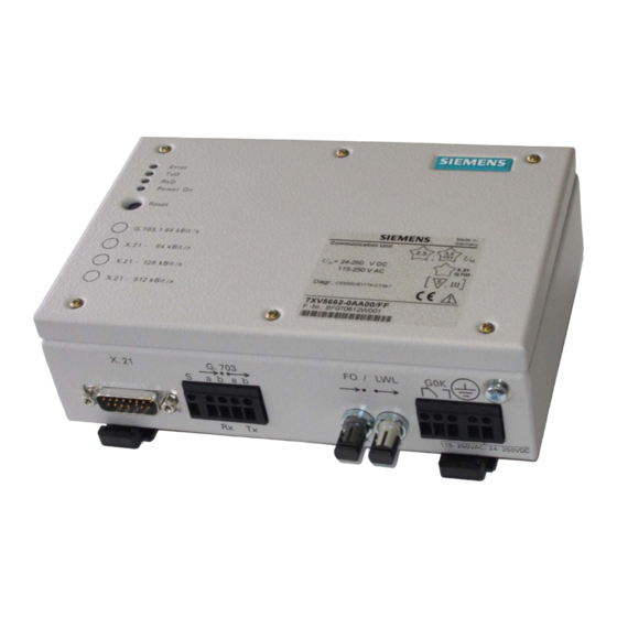
Page 10: Anschlüsse
Deutsch 7XV5662-0AA00 Ein Kontaktausgang (Relaiskontakt, Wechsler) dient zur Erzeugung eines „Gerät–Ok”– Signals (GOK). Nur bei angezogenen Relais ist das Gerät zur Datenkommunikation bereit. Der Öffner meldet eine Störung. Alle Betriebszustände werden über LEDs signalisiert. Anschlüsse Bild 3 Schnittstellen und Anschlüsse Auf der Geräteseite (Bild 3) befinden sich folgende Schnittstellen und Anschlüsse:... -
Page 11: Anschlusshinweise
7XV5662-0AA00 Deutsch GOK für X.21 In dieser Schnittstellenart müssen folgende Bedingungen erfüllt sein, damit GOK aktiviert wird: Power–Fail–Signal ist inaktiv (internes Netzteil ist in Ordnung). RESET–Signal ist inaktiv (interne Logik ist in Ordnung). Indication–Signal der Schnittstelle ist aktiv. GOK für G.703.1 In dieser Schnittstellenart müssen folgende Bedingungen erfüllt sein:... - Page 12 Deutsch 7XV5662-0AA00 Die Anschlussdrähte sind um 6 mm abzuisolieren, bis zum Anschlag in die Schraubklemme einzuführen und so zu sichern, dass sie beim Festschrauben nicht wieder herausgeschoben werden. Nach dem Anschrauben sind die Anschlüsse auf festen Sitz hin zu überprüfen.
- Page 13 7XV5662-0AA00 Deutsch DSUB–Stecker Für die Schnittstelle X.21 dient ein 15-poliger DSUB–Stecker als Anschluss (Bild 5). Als Anschlussbuchsen können alle handelsüblichen 15-poligen DSUB–Buchsen nach MIL–C– 24308 und DIN 41652 verwendet werden. X.21 auf der Geräteseite Bild 5 DSUB–Stecker Die 15-adrige Datenleitung soll verdrillt und geschirmt ausgeführt sein. Die Pinbelegung geht aus Bild 6 hervor.
- Page 14 Deutsch 7XV5662-0AA00 Lichtwellenleiter Die LWL–Anschlüsse (Bild 7) sind mit Abdeckhauben versehen, die eine Verschmutzung vermeiden. Sie lassen sich durch eine Linksdrehung um 90° abnehmen. Warnung! Nicht direkt in die Lichtwellenleiter- elemente schauen! 1-kanalig Bild 7 LWL–Anschlüsse für Sende- und Empfangsrichtung LWL–Stecker Typ:...
-
Page 15: Montage
7XV5662-0AA00 Deutsch Montage Bevor Sie mit der Installation beginnen, vergewissern Sie sich, dass folgende Zubehör- teile vorhanden sind: geschirmtes Schnittstellenkabel (min. 10-pol. für X.21 oder 4-poliges für G.703.1), Handbuch zum Schutzgerät, Beipack mit Ferriten und Installationsanweisung. Führen Sie die dem Gerät beiliegende Installationsanweisung durch! beidseitig mit ST–Steckern konfektionierte Lichtwellenleiter,... -
Page 16: Inbetriebsetzung
Deutsch 7XV5662-0AA00 Inbetriebsetzung Hinweis: Der Kommunikationsumsetzer wird mit den Jumperstellungen „X.21” und „64 kBit/s” ausgeliefert. Öffnen des Kommunikationsumsetzers Schalten Sie die Hilfsspannung beidpolig ab. GEFAHR! Vor dem Öffnen des Kommunikationsumsetzers ist dieser unbe- dingt von der Hilfsspannung allpolig zu trennen! Es besteht Le- bensgefahr durch spannungsführende Teile. - Page 17 7XV5662-0AA00 Deutsch BETRIEBSART BITRATE X.21 Bild 8 Lokalisierung der Jumper (Lieferstellung) Testmodus: Mit dem Jumper X32 kann die Testfunktion aktiviert werden, dieser muss während des Normalbetriebes auf X32 (1–2) stecken, Teststellung ist 2–3. Die Testfunktion ist für eine einfache Inbetriebsetzung bzw. Serviceaufgaben gedacht. In dieser Betriebsart durchlaufen keine Signale den Kommunikationsumsetzer (Bild 9).
- Page 18 Deutsch 7XV5662-0AA00 Schnittstelle KU–XG − − − Logik1 Logik2 X.21 G.703.1 − − − Logik2 Logik1 Bild 9 Betriebsart Test Einstellungen im Schutzgerät In den Schutzgeräten 7SD52, 7SD610, 7SA52 oder 7SA6 muss die Wirkschnittstelle auf „vorhanden” konfiguriert sein, über die die Kommunikation mit dem gegenüberliegenden Schutzgerät läuft.
- Page 19 7XV5662-0AA00 Deutsch LED3, RxD Die gelbe LED „RxD” signalisiert die Empfangsdaten (LWL–R), die vom Schutzgerät kommen und zur Netzschnittstelle übertragen werden sollen. LED4, Power On Die grüne LED „Power On” signalisiert die zugeschaltete Hilfsspannung. Taster Der Taster löst einen Reset aus.
- Page 20 Deutsch 7XV5662-0AA00 Schritt 3 : Am KU–XG1 die LWL–Kabel anschließen, Schutzkommunikation starten KU–XG1 KU–XG2 LED1 LED1 LED2 LED2 LED3 BLINKT LED3 LED4 LED4 Schritt 4 : KU–XG2 Power On KU–XG1 KU–XG2 LED1 LED1 LED2 LED2 LED3 BLINKT LED3 LED4 LED4 Schritt 5 : Am KU–XG2 die Schnittstelle (X.21 / G.703) auflegen...
-
Page 21: Technische Daten
7XV5662-0AA00 Deutsch Technische Daten Hilfsspannung Spannungsversorgung über Weitbereichsnetzteil Gleichspannung Nennhilfsgleichspannung U – 24 V– bis 250 V– zulässige Spannungsbereich 19 V– bis 300 V– Leistungsaufnahme ca. 3,5 W überlagerte Wechselspannung, ≤ 12 % bei Nennspannung, IEC 60255–11 Spitze–Spitze Überbrückungszeit bei Ausfall/Kurzschluss ≥... - Page 22 Deutsch 7XV5662-0AA00 Schnittstelle zum Schutzgerät Lichtwellenleiter (LWL) – LWL–Stecker Typ ST–Stecker λ = 820 nm – optische Wellenlänge bei Einsatz Glasfaser 62,5/125 μm – Laserklasse 1 nach EN 60825–1/ –2 max. 8 dB, bei Glasfaser 62,5/125 μm – zulässige Streckendämpfung –...
- Page 23 7XV5662-0AA00 Deutsch – Stoßspannungsprüfung (Typprüfung) 5 kV (Scheitel); 1,2/50 µs; 0,5 J; 3 positive alle Kreise, außer Kommunikations- und 3 negative Stöße in Abständen von 5 s und Zeitsynchronisations- Schnittstellen, Klasse III EMV-Prüfungen zur Störfestigkeit (Typprüfungen) Normen: IEC 60255-6 und -22, (Produktnormen)
- Page 24 Deutsch 7XV5662-0AA00 – Energiereiche Stoßspannungen (SURGE) IEC 61000-4-5, Installationsklasse 3 Impuls: 1,2/50 µs common mode: 2 kV; 12 Ω; 9 µF Hilfsspannung diff. mode: 1 kV; 2 Ω; 18 µF common mode: 2 kV; 42 Ω; 0,5 µF Relaisausgang (GOK) common mode: 2 kV;...
- Page 25 7XV5662-0AA00 Deutsch Mechanische Prüfungen Schwing- und Schockbeanspruchung bei stationärem Einsatz Normen: IEC 60255-21 und IEC 60068-2 – Schwingung sinusförmig 10 Hz bis 60 Hz: ± 0,075 mm Amplitude IEC 60255-21-1, Klasse 2 IEC 60068-2-6 60 Hz bis 150 Hz: 1 g Beschleunigung...
- Page 26 Deutsch 7XV5662-0AA00 Klimabeanspruchungen Temperaturen IEC 60068–2 – empfohlene Temperatur bei Betrieb –5 °C bis +55 °C – vorübergehend zulässige Grenztem- –20 °C bis +70 °C peraturen bei Betrieb – Typprüfung (nach IEC 60068–2–1 und –2 –25 °C bis +85 °C Test Bd für 16 h)
-
Page 27: Maßbilder Bis Hardwareausgabestand /Ee
7XV5662-0AA00 Deutsch Maßbilder bis Hardwareausgabestand /EE An der Wand montierte Hutschiene gehört nicht zum Lieferumfang Kreuzschlitzschraube Entriegelung Maße in mm ) Hutschienenmindestlänge ) Maßbild gilt für Hutschiene IEC / EN 60715; 35 x 7,5 Bild 10 Abmessungen des Kommunikationsumsetzers bis Hardwareausgabestand /EE... -
Page 28: Maßbilder Ab Hardwareausgabestand /Ff
Deutsch 7XV5662-0AA00 Maßbilder ab Hardwareausgabestand /FF L ≥ 188 13,5 Hinweis: Bitte beachten Sie, dass es kleine Unterschiede in den Abmessungen bei Ge- räten ab Hardwareausgabestand /FF gegenüber Geräten bis einschließlich Hardwareausgabestand /EE gibt. An der Wand montierte Hutschiene gehört nicht zum Lieferumfang... - Page 29 7XV5662-0AA00 English Contents Statement of Conformity ....................30 Notes and Warnings ......................30 Unpacking and Re-packing ..................... 32 Storage and Transport ....................32 Application ........................33 Features .......................... 34 Function .......................... 35 Connections ........................36 Connection Instructions ....................37 Installation ........................41 Commissioning ........................
-
Page 30: Statement Of Conformity
This conformity has been proved by tests performed according to Article 10 of the Council Directive in agreement with the generic standards EN 61000-6-2 and EN 61000-6-4 (for EMC directive) and with the standards EN 60255-6 (for low-voltage directive) by Siemens The device is designed and manufactured for application in industrial environment. - Page 31 7XV5662-0AA00 English Warning! Hazardous voltages are present in this electrical equipment during operation. Non-observance of the safety rules can result in severe personal injury or property damage. Only qualified personnel shall work on and around this equipment after becoming thoroughly familiar with all warnings and safety notices of this booklet as well as with the applicable safety regulations.
-
Page 32: Unpacking And Re-Packing
English 7XV5662-0AA00 Unpacking and Re-packing When dispatched from the factory, the equipment is packed in accordance with the guide- lines laid down in IEC 60255–21 which specify the impact resistance of packaging. This packing shall be removed with care, without force and without the use of inappropriate tools. -
Page 33: Application
7XV5662-0AA00 English Application The communication converter (KU–XG) is a peripheral device connected to the protection device, which allows serial data exchange between two protection devices. A communicati- on network is used for this purpose. The digital synchronous interfaces X.21 and G.703–... -
Page 34: Features
English 7XV5662-0AA00 Features The communication converter has the following characteristics: Transmission speed for X.21 selectable between 64, 128, 256 and 512 kBit/s. Transmission speed for G.703.1 64 kBit/s. Connection to the protection device via fibre optic cable to a FO5 module integrated there. -
Page 35: Function
7XV5662-0AA00 English Function Grounding screw Reset Internal logic Optical fibre, transmit G.703, transmit Optical fibre, receive G.703, receive Error G.703, screen X.21, DSUB Power On Figure 13 Hardware structure of the communication converter The task of the communication converter is to perform an adaptation of the available fibre optic active interface in the protection device (DTE) to the physical specification of the respective interface of the communication network (DCE). -
Page 36: Connections
English 7XV5662-0AA00 A contact output (relay contact, changeover contact) generates a “device ready” signal (GOK / DR). Only when a relay has picked up the device is ready for data communication. The NC contact signals a fault. All operating states are signalled via LEDs. -
Page 37: Connection Instructions
7XV5662-0AA00 English GOK / DR for X.21 In this interface type, the following conditions must be fulfilled so that DR is activated: Power–Fail signal is inactive (internal power supply unit is in proper condition). RESET signal is inactive (internal logic is in proper condition). - Page 38 English 7XV5662-0AA00 Strip the connecting wires to a length of 6 mm, insert them into the screw terminals as far as they will go in, and secure them so that they will not slip out while tightening the screw. After tightening the screws, verify that the wires to the terminals are tightly connected.
- Page 39 7XV5662-0AA00 English DSUB–connector A 15-pole DSUB–connector serves as the connection for the interface X.21 (Figure 16). Standard 15-pin D-subminiature plug connectors conforming to MIL–C–24308 and DIN 41652 can be used. X.21 on the device side Figure 16 DSUB–connector The 15-strand data line should be twisted and screened. The pin assignment can be seen in Figure 17.
- Page 40 English 7XV5662-0AA00 Optical Fibres The fibre-optic links (Fig.7) are provided with cover caps to prevent the ingress of dirt. They can be removed by turning them 90° counterclockwise. Warning! Do not look directly into the fibre- optic elements! 1 channel...
-
Page 41: Installation
7XV5662-0AA00 English Installation Before commencing installation, ensure that the following accessory parts are available: screened Interface cable (min. 10-pole for X.21 or 4-pole for G.703.1), Manual for the protection device, Installation kit with ferrite rings and installation guide. Please follow the installation guide. -
Page 42: Commissioning
English 7XV5662-0AA00 Commissioning Note: The communication converter is delivered with the jumper settings “X.21” and “64 kBit/s”. Open the communication converter Disconnect the auxiliary supply voltage from both poles. DANGER! Before opening the communication converter, it is absolutely ne- cessary to isolate it from the auxiliary supply voltage at all poles! Energized parts pose a potentially lethal hazard! Open the communication converter. - Page 43 7XV5662-0AA00 English BITRATE X.21 OPERATING MODE Figure 19 Localizing the jumper (factory setting) Test mode The Test function can be activated with the jumper X32. This must be plugged to X32 (1–2) during normal operation, the Test position is 2–3.
- Page 44 English 7XV5662-0AA00 Interface KU–XG − − − Optical fibre Logic1 Logic2 X.21 G.703.1 − − − Optical fibre Logic1 Logic2 Figure 20 Test mode Settings in the protection device In protection devices 7SD52, 7SD610, 7SA52 or 7SA6, the active interface enables the communication with the opposite protection device must be configured to “enabled”.
- Page 45 7XV5662-0AA00 English LED3, RxD The yellow LED “RxD” signals the received data (optical fibre –R), that comes from the protection device and is to be transmitted to the mains interface. LED4, Power On The green LED “Power On” signals the activated auxiliary voltage.
- Page 46 English 7XV5662-0AA00 Step 3 At KU–XG1, connect the fibre-optic cable and start protection communication KU–XG1 KU–XG2 LED1 BREAK LED1 BREAK LED2 LED2 BREAK LED3 FLASHING LED3 BREAK LED4 MAKE LED4 BREAK Step 4 KU–XG2 Power On KU–XG1 KU–XG2 LED1 BREAK...
-
Page 47: Technical Data
7XV5662-0AA00 English Technical Data Auxiliary voltage Voltage supply via extended range power supply unit DC voltage Rated auxiliary voltage U – 24 V– to 250 V– Perm. voltage range 19 V– to 300 V– Power input approx. 3.5 W Permissible AC ripple voltage, ≤... - Page 48 English 7XV5662-0AA00 Interface to the protection device Optical fibre – Fibre-optic plug type ST–plug λ = 820 nm – Optical wavelength for use of FO 62.5/125 μm – Laser class 1 acc. to EN 60825–1/ –2 – Permissible optical link signal max.
- Page 49 7XV5662-0AA00 English Electrical Tests Specifications Standards: IEC 60255 (Product Standards) ANSI/IEEEC37.90.0,.C37.90.0.1, C37.90.0.2 DIN 57435 Part 303 See also standards for individual tests Insulation Tests Standards: IEC/EN 61010-1, IEC 60255-5 and IEC 60870-2-1 – High Voltage Test (routine test) DC 3.5 kV only power supply and GOK –...
- Page 50 English 7XV5662-0AA00 – Fast Transient Disturbance Burst 4 kV all circuits/2 kV communication, IEC 60255-22-4, Class A if guidelines of installation are fullfilled IEC 61000-4-4, Class IV for life contact if G703.1 port is used, up to 3 kV burst;...
- Page 51 7XV5662-0AA00 English EMC Tests For Noise Emission (Type Test) Standard: EN 61000-6-3 (Generic Standard) – Radio Noise Voltage and Current 150 kHz to 30 MHz to Lines Limit Class B IEC-CISPR 22 – Radio Noise Field Strength 30 MHz to 1000 MHz...
- Page 52 English 7XV5662-0AA00 Vibration and Shock Stress During Transport Standards: IEC 60255-21 and IEC 60068-2 – Vibration Sinusoidal 5 Hz to 8 Hz: ± 7.5 mm Amplitude IEC 60255-21-1, Class 2 IEC 60068-2-6 8 Hz to 150 Hz: 2 g acceleration Frequency sweep rate 1 Octave/min 20 cycles in 3 orthogonal axes.
- Page 53 7XV5662-0AA00 English Construction Housing Dimensions 188 mm × 120 mm × 55 mm (W × D × H) (s. Figures 21 and 22) Weight approx. 0.8 kg Degree of protection according to EN 60529 Housing IP 41 Interface side IP 2x...
-
Page 54: Dimensioned Drawings Up To Hardware Version /Ee
English 7XV5662-0AA00 Dimensioned drawings up to hardware version /EE Mounting rails mounted on the wall are not included in the scope of delivery Cross recess screw Unlocking Dimensions in mm ) Minimum mounting rail length ) The dimensioned drawing applies to the standard mounting rail IEC / EN 60715; 35 x 7.5... -
Page 55: Dimensioned Drawings From Hardware Version /Ff
7XV5662-0AA00 English Dimensioned drawings from hardware version /FF L ≥ 188 13.5 Note: Please note that there are minor differences in the dimensions of devices from the hardware version /FF as compared with devices up to the hardware version /EE. - Page 56 English 7XV5662-0AA00 C53000-B1174-C134-7...
- Page 57 7XV5662-0AA00 C53000-B1174-C134-7...
- Page 58 All Rights are reserved in the event of the grant of a patent or registration of a utility model or Subject to technical alteration design. Release 04.20.01 SIEMENS AKTIENGESELLSCHAFT C53000-B1174-C134-7 Bestell-Nr./Order-No.: Bestellort/Available from: PTD EA Bln W5 Printed in Germany/Imprimé...
Need help?
Do you have a question about the 7XV5662-0AA00 and is the answer not in the manual?
Questions and answers