Table of Contents
Advertisement
Available languages
Available languages
7XV5662-0AA00/GG
Handbuch/Manual
Hinweise für den Gebrauch
Kommunikationsumsetzer - X.21/G.703.1
Synchrone und asynchrone Schnittstelle
Directions for use
Communication Converter - X.21/G.703.1
Synchronous and asynchronous interface
Copyright Siemens AG 2013
Bestell-Nr./Order No.: C53000-B1174-C134-8
Deutsch: Seite 3
English: Page 31
Advertisement
Chapters
Table of Contents

Related Manuals for Siemens 7XV5662-0AA00/GG


Summary of Contents for Siemens 7XV5662-0AA00/GG
- Page 1 7XV5662-0AA00/GG Handbuch/Manual Bestell-Nr./Order No.: C53000-B1174-C134-8 Hinweise für den Gebrauch Deutsch: Seite 3 Kommunikationsumsetzer - X.21/G.703.1 Synchrone und asynchrone Schnittstelle Directions for use English: Page 31 Communication Converter - X.21/G.703.1 Synchronous and asynchronous interface Copyright Siemens AG 2013...
- Page 2 Deutsch 7XV5662-0AA00/GG C53000-B1174-C134-8...
-
Page 3: Table Of Contents
7XV5662-0AA00/GG Deutsch Inhalt Angaben zur Konformität ....................4 Hinweise und Warnungen ....................4 Gerät auspacken ....................... 5 Gerät wiederverpacken ..................... 6 Gerät einlagern ......................... 6 Transport ........................... 6 Fehlersuche, Instandsetzung, Reinigung ................7 Verwendung ........................7 Merkmale .......................... 9 Funktion .......................... 10 Anschlüsse ........................ -
Page 4: Angaben Zur Konformität
Betriebsmittel zur Verwendung innerhalb bestimmter Spannungsgrenzen (Niederspanungs- richtlinie 2006/95/EG). Diese Konformität ist das Ergebnis einer Prüfung, die durch die Siemens AG gemäß Artikel10 der Richtlinie in Übereinstimmung mit den Fachgrundnormen EN 61000-6-2 und EN 61000-6-4 für die EMV-Richtlinie und der Norm EN 60950-1 für die Niederspannungs- richtlinie durchgeführt worden ist. -
Page 5: Gerät Auspacken
7XV5662-0AA00/GG Deutsch Warnung! Beim Betrieb elektrischer Geräte stehen zwangsläufig bestimmte Teile dieser Geräte unter gefährlicher Spannung. Es können deshalb schwe- re Körperverletzung oder Sachschaden auftreten, wenn nicht fachge- recht gehandelt wird. Nur entsprechend qualifiziertes Personal soll an diesem Gerät oder in dessen Nähe arbeiten. -
Page 6: Gerät Wiederverpacken
-40 °C bis +85 °C. Die relative Luftfeuchte darf weder zur Kondenswasser- noch zur Eisbildung führen. Siemens empfiehlt, bei der Lagerung einen eingeschränkten Temperaturbereich zwischen +10 °C und +35 °C einzuhalten, um einer vorzeitigen Alterung der in der Stromversorgung eingesetzten Elektrolytkondensatoren vorzubeugen. -
Page 7: Fehlersuche, Instandsetzung, Reinigung
7XV5662-0AA00/GG Deutsch Fehlersuche, Instandsetzung, Reinigung Eine Instandsetzung des defekten Gerätes durch den Benutzer ist unzulässig, da spezielle elektronische Bauelemente eingesetzt sind, die nach den Richtlinien für elektrostatisch gefährdete Bauelemente (EGB) ausschließlich durch den Hersteller zu behandeln sind. Außerdem können gefährliche Spannungen bei unkorrekter Arbeitsweise zu tödlichen Verletzungen führen. - Page 8 Deutsch 7XV5662-0AA00/GG Geräte müssen mit dem optischen Modul USART-AD-1FO oder USART-AE-2FO be- stückt sein. Asynchroner serieller Datenaustausch zwischen zwei Geräten des selben Typs: ® SIPROTEC 3 : Differentialschutz (7SD51). Binärsignalübertrager, SICAM I/O-Unit (7XV5653, 7XV5673): Punkt-zu-Punkt-Übertragung binärer Signale z.B. für seriell Signalvergleichslogik beim Distanzschutz.
-
Page 9: Merkmale
7XV5662-0AA00/GG Deutsch Merkmale Der Kommunikationsumsetzer hat folgende Merkmale: Synchron: Übertragungsgeschwindigkeit für X.21 64 kBit/s, 128 kBit/s, 256 kBit/s oder 512 kBit/s nutzbar. Übertragungsgeschwindigkeit für G.703.1 64 kBit/s. Asynchron: Asynchrone Übertragungsgeschwindigkeit der Daten bei X.21 64 kBit/s von 0,3 kBaud bis 19,2 kBaud,... -
Page 10: Funktion
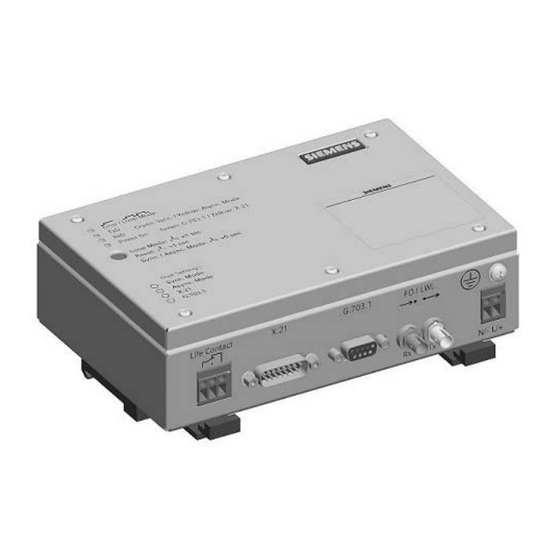
Deutsch 7XV5662-0AA00/GG Funktion Erdungsschraube Reset, Mode Interne Logik Life Contact LWL, Senden LWL, Empfängen G.703.1, DSUB Error X.21, DSUB Power On Bild 2 Hardware-Struktur des Kommunikationsumsetzers Die Aufgabe des Kommunikationsumsetzers besteht darin, eine Anpassung der verfügbaren LWL-Wirkschnittstelle im Schutzgerät (DEE) an die physikalische Spezifikation der jeweili- gen Schnittstelle des Kommunikationsnetzes (DÜE) vorzunehmen. -
Page 11: Anschlüsse
7XV5662-0AA00/GG Deutsch Ein Kontaktausgang (Relaiskontakt, Wechsler) dient zur Erzeugung eines „Gerät-OK”- Signals (Life Contact). Nur bei angezogenen Relais ist das Gerät zur Datenkommunikation bereit. Der Kontakt meldet eine Störung. Im folgenden Abschnitt finden Sie die Bedingungen damit das Relais anzieht. -
Page 12: Anschlusshinweise
Deutsch 7XV5662-0AA00/GG RESET-Signal ist inaktiv (interne Logik ist in Ordnung). Indication-Signal der Schnittstelle ist aktiv. Netztakt des Kommunikationsgerätes (DÜE) als gültig erkannt. Beide Kommunikationsumsetzer haben sich synchronisiert. Life Contact für G.703.1 In dieser Schnittstellenart müssen folgende Bedingungen erfüllt sein: Power-Fail-Signal ist inaktiv (Netzteil und Hilfsspannung sind in Ordnung). - Page 13 7XV5662-0AA00/GG Deutsch Die Anschlussdrähte sind um 6 mm abzuisolieren, bis zum Anschlag in die Schraubklemme einzuführen und so zu sichern, dass sie beim Festschrauben nicht wieder herausgezogen werden. Nach dem Anschrauben sind die Anschlüsse auf festen Sitz hin zu überprüfen.
- Page 14 Deutsch 7XV5662-0AA00/GG *) wird nicht verwendet Bild 6 Pinbelegung des 15-poligen Datenkabels DSUB-Buchse Für die Schnittstelle G.703.1 dient eine 9-polige DSUB-Buchse als Anschluss. Als An- schlussbuchsen können alle handelsüblichen 9-poligen DSUB-Stecker nach MIL-C-24308 und DIN 41652 verwendet werden. Bild 7...
- Page 15 7XV5662-0AA00/GG Deutsch Die 4-adrige Datenleitung soll verdrillt und geschirmt ausgeführt sein. Die Pinbelegung geht aus Bild 8 hervor. Zwischen Kommunikationsumsetzer und G.703.1-Schnittstelle des Kom- munikationsnetzes werden kurze Verbindungen empfohlen, um elektrische Störbeeinflus- sungen zu vermeiden. Der Kommunikationsumsetzer muss in der Nähe des Kommuni- kationsgerätes (DÜE) installiert werden.
-
Page 16: Montage
Deutsch 7XV5662-0AA00/GG Zulässige Biegeradien: für Innenkabel = 5 cm für Außenkabel = 20 cm Hinweis:Die Laserklasse 1 wird nach EN 60825-1 und EN 60825-2 eingehalten bei Fasertyp . 62,5 µm/125 µm und 50 µm/125 µm . Montage Bevor Sie mit der Installation beginnen, vergewissern Sie sich, dass folgende Zubehör- teile vorhanden sind: geschirmtes Schnittstellenkabel gemäß... - Page 17 7XV5662-0AA00/GG Deutsch Stecken Sie das andere Ende des Kabels in das von Ihnen gewählte Kommunika- tionsgerät. Achten Sie unbedingt auf die korrekte Verdrahtung zwischen den Schnittstellen und das beidseitige Auflegen des Schirmes. Verbinden Sie die Sendeleitung Ihres Schutzgerätes mit dem Empfangsanschluss des Kommunikationsumsetzers.
-
Page 18: Anzeige Und Bedienung
Deutsch 7XV5662-0AA00/GG Bild 11 Montageansicht: Seitenansicht Anzeige und Bedienung Es sind vier Anzeige- und ein Bedienelement am KU-XG vorhanden. Diese befinden sich auf der Oberseite des Gehäuses (siehe Bild 10). Die vier LEDs sind zweifarbig ausgelegt. LED1, Error / Loop Mode Die LED signalisiert unmittelbar die Funktionsweise des Life Contact-Relais. -
Page 19: Inbetriebsetzung
7XV5662-0AA00/GG Deutsch Betriebsfarbe ’Gelb’: Gerät arbeitet im asynchronen Mode. LED4, Power On Die LED „Power On” signalisiert die zugeschaltete Hilfsspannung. Betriebsfarbe ’Grün’: Gerät kommuniziert über die G.703.1 Schnittstelle Betriebsfarbe ’Gelb’: Gerät kommuniziert über die X21 Schnittstelle Taster Mit Hilfe des Tasters können die einzelnen Arbeitsmodis umgeschaltet werden. - Page 20 Deutsch 7XV5662-0AA00/GG Schnittstelle KU-XG − − − Logik1 Logik2 X.21 G.703.1 − − − Logik2 Logik1 Bild 12 Betriebsart Test Weitere Einzelheiten über das Vorgehen bei der Inbetriebsetzung eines Schutzgerätes mit dem Kommunikationsumsetzer entnehmen Sie bitte dem Gerätehandbuch des Schutzge- rätes unter dem Abschnitt „Montage und Inbetriebsetzung”.
-
Page 21: Technische Daten
7XV5662-0AA00/GG Deutsch Technische Daten Hilfsspannung Spannungsversorgung über Weitbereichs- netzteil Gleichspannung Nennhilfsgleichspannung V 24 V bis 250 V Zulässige Spannungsbereich 19 V bis 300 V Stromaufnahme, max. 150 mA Leistungsaufnahme, max. 2,9 W Überlagerte Wechselspannung IEC 61000-4-17, IEC 60255-11 ≤ Spitze-Spitze 12 % bei Nennspannung Überbrückungszeit bei Ausfall/Kurzschluss... - Page 22 Deutsch 7XV5662-0AA00/GG Schnittstelle zum Schutzgerät Lichtwellenleiter (LWL) LWL-Stecker-Typ ST-Stecker Optische Wellenlänge λ = 820 nm Baudrate 64 kBit/s, 128 kBit/s, 256 kBit/s oder 512 kBit/s Empfängerempfindlichkeit (peak) optische Leistung für High-Pegel max. -40 dBm optische Leistung für Low-Pegel min. -24 dBm Optical Power Budget min.
- Page 23 7XV5662-0AA00/GG Deutsch Schnittstellen zum Kommunikationsgerät X.21 Anschluss 15-poliger DSUB-Stecker, potentialfrei Übertragungsrate, synchron 64 kBit/s, 128 kBit/s, 256 kBit/s oder 512 kBit/s Übertragungsrate, asynchron max.115,2 kBaud bei 512 kbit/s (s. Kapitel Merkmale) Kabel siehe Abschnitte Anschlusshinweise, Installationsanweisung und Montage G.703.1 Anschluss 9-polige DSUB-Buchse, potentialfrei Übertragungsrate, synchron...
- Page 24 Deutsch 7XV5662-0AA00/GG Isolationskoordination entsprechend IEC / EN / UL 61010-1 Überspannungs-Kategorie III, Verschmutzungsgrad 2 EMV-Prüfungen zur Störfestigkeit IEC/EN 61000-6-2 , IEC 60255 -22, (Pro- duktnormen) Normen VDE 0435 Weitere Normen siehe Einzelprüfungen 2,5 kV (Scheitel); 1 MHz; τ = 15 μs; 400 1 MHz Prüfung, Klasse III IEC 60255-22-1,...
- Page 25 7XV5662-0AA00/GG Deutsch IEC 61000-4-18 2,5 kV (Scheitel); 100 kHz; 40 Stöße je s; Prüfdauer 2 s; Ri = 200 Ω Radiated Electromagnetic Interference 20 V/m; 80 MHz bis 1 GHz; 80 % AM; 1 kHz Gedämpfte Schwingungen IEEE Std C37.90.2 EMV-Prüfungen zur Störaussendung (Typprüfung)
- Page 26 Deutsch 7XV5662-0AA00/GG Schwingen bei Erdbeben Sinusförmig IEC 60255-21-3, Klasse 1; 1 Hz bis 8 Hz: ± 3,5 mm Amplitude (horizon- tale Achse) IEC 60068-3-3 1 Hz bis 8 Hz: ± 1,5 mm Amplitude (vertikale Achse) 8 Hz bis 35 Hz: 1 g Beschleunigung...
- Page 27 7XV5662-0AA00/GG Deutsch empfohlene Temperaturbereich bei Lage- +10 °C bis +35 °C rung zulässige Temperaturbereich bei Lagerung –40 °C bis +85 °C zulässige Temperaturbereich bei Transport –40 °C bis +85 °C Feuchte zulässige Feuchtebeanspruchung im Jah- = 75 % relative Feuchte;...
-
Page 28: Maßbilder
Deutsch 7XV5662-0AA00/GG Maßbilder Bild 13 Abmessungen des Kommunikationsumsetzers Front- und Seitenansich C53000-B1174-C134-8... - Page 29 7XV5662-0AA00/GG English Contents Statement of Conformity ....................32 Notes and Warnings ......................32 Unpacking a Device ......................33 Repacking a Device ......................34 Storing a Device ......................34 Transport ......................... 34 Troubleshooting, Repair, Cleaning .................. 35 Application ........................35 Features .......................... 37 Function ..........................
-
Page 30: Statement Of Conformity
This conformity has been proved by tests performed according to Article 10 of the Council Directive in agreement with the generic standards EN 61000-6-2 and EN 61000-6-4 (for EMC directive) and with the standards EN 60950-1 (for low-voltage directive) by Siemens The device is designed and manufactured for application in industrial environment. -
Page 31: Unpacking A Device
7XV5662-0AA00/GG English Warning! Hazardous voltages are present in this electrical equipment during operation. Non-observance of the safety rules can result in severe personal injury or property damage. Only qualified personnel shall work on and around this equipment after becoming thoroughly familiar with all warnings and safety notices of this booklet as well as with the applicable safety regulations. -
Page 32: Repacking A Device
The relative humidity must be at a level where condensate and ice is prevented from forming. Siemens recommends that you observe a restricted storage temperature range of +10 °C to +35 °C (50 °F to 95 °F), in order to prevent the electrolytic capacitors used in the power supply from aging prematurely. -
Page 33: Troubleshooting, Repair, Cleaning
If you suspect that the device has a defect, Siemens recommends to send the entire device back to the manufacturer. If possible, use the original transport packaging or an equivalent packaging. - Page 34 English 7XV5662-0AA00/GG ® SIPROTEC 3: differential protection (7SD51). Binary signal transmitter, SICAM I/O-Unit : bidirectional transmission of binary signals e.g. for teleprotection (7XV5653, 7XV5673). Communication network Communication Communication converter device Protection X.21 CC-XG1 optical device G.703.1 electrical X.21 G.703.1 ➁...
-
Page 35: Features
7XV5662-0AA00/GG English Features The communication converter has the following features: Synchronous: Transmission rate for X. 21 64 Kbit/s, 128 Kbit/s, 256 Kbit/s or 512 Kbit/s usable. Transmission rate for G.703.1 64 Kbit/s. Asynchronous: Asynchronous transmission rate of the data at X. 21 64 Kbit/s from 0.3 kBaud to 19.2 kBaud,... -
Page 36: Function
English 7XV5662-0AA00/GG Function Grounding screw Reset, mode Internal logic Life Contact Optical fibre, transmit Optical fibre, receive G.703.1, DSUB Error X.21, DSUB Power On Figure 2 Hardware structure of the communication converter The task of the communication converter is to perform an adaptation of the available fibre optic active interface in the protection device (DTE) to the physical specification of the respective interface of the communication network (DCE). -
Page 37: Connections
7XV5662-0AA00/GG English A contact output (relay contact, changeover contact) generates a "device ready" signal (life contact). Only when the relay has picked up, the device is ready for data communication. The contact signals a fault. All operating states are signalled via LEDs. -
Page 38: Connection Instructions
English 7XV5662-0AA00/GG Network clock pulse of the communication device (DCE) as valid recognized. Both communication converters have synchronized themselves. Life Contact for G.703.1: In this interface type, the following conditions must be fulfilled: Power-Fail signal is inactive (internal power supply unit is in proper condition). - Page 39 7XV5662-0AA00/GG English Signal connections The data cable for X.21 or G.703.1 interface has to be at least of the type S/UTP (Screened Unshielded Twisted Pair). An S/UTP-cable consists of a plastic sheath and a full length screen which contain the cores stranded in pairs. The screen may be a copper braid or aluminium foil or both.
- Page 40 English 7XV5662-0AA00/GG Figure 6 Pin assignment of the 15-pole data cable D SUB-socket A 9-pole D SUB-socket serves as the connection for the interface G.703.1 (Figure 7). Standard 9-pin D-subminiature plug connectors conforming to MIL-C-24308 and DIN 41 652 can be used.
- Page 41 7XV5662-0AA00/GG English The 4-strand data line should be twisted and screened. The pin assignment can be seen in Figure 8. Between the communication converter and the G.703.1 interface of the communi- cation device, it is recommended to have short connenctions, in order to avoid electrical interferences.
-
Page 42: Installation
English 7XV5662-0AA00/GG λ = approx. 820 nm Wavelength: Perm. bending radii: for indoor cables = 5 cm (2 in) for outdoor cables = 20 cm (8 in) Note: Class 1 as defined by EN 60825-1 is met in the case of fibre type 62.5 µm/125 µm or 50 µm/125 µm . - Page 43 7XV5662-0AA00/GG English Connect the transmit line of your protection device to the receive interface module of the communication converter. Connect the second terminal, the receive interface module of your protection device, to the transmit interface module of the communication converter.
-
Page 44: Display And Operation
English 7XV5662-0AA00/GG Figure 11 assembly view: sideview Display and operation The CC-XG is equipped with four display elements and one control element. They are located on the upper side of the housing (see Figure 10). The four LEDs are bicolour. -
Page 45: Commissioning
7XV5662-0AA00/GG English Operating colour 'yellow': the device operates in asynchronous mode. LED4, Power On The LED "Power On" signals that the auxiliary voltage is active. Operating colour 'green': The device communicates via the G.703.1 interface. Operating colour 'yellow': The device communicates via the X.21 interface. - Page 46 English 7XV5662-0AA00/GG Interface CC-XG − − − Optical fibre Logic1 Logic2 X.21 G.703.1 − − − Optical fibre Logic1 Logic2 Figure 12 Test mode For more information on the commissioning procedure of a protection device with the communication converter, refer to the device manual of the protection device, section "Mounting and Commissioning".
-
Page 47: Technical Data
7XV5662-0AA00/GG English Technical Data Auxiliary voltage Voltage supply via wide area power supply Direct voltage Nominal auxiliary DC voltage V 24 V to 250 V Permissible voltage ranges 19 V to 300 V Current consumption, max. 150 mA Power consumption, max. - Page 48 English 7XV5662-0AA00/GG Interface to the protetion device Fiber optic cable (FO) FO connector type ST connector Optical wavelength λ = 820 nm Baud rate 64 kBit/s, 128 kBit/s, 256 kBit/s or 512 kBit/s Receiver sensitivity (peak) optical power for high-level max.
- Page 49 7XV5662-0AA00/GG English Interfaces to a communication device X.21 Terminal 15-pole DSUB plug, potential-free Transmission rate, synchron 64 kBit/s, 128 kBit/s, 256 kBit/s or 512 kBit/s Transmission rate, asynchron max.115,2 kBaud at 512 kbit/s (see chapter Features) Cable see chapter Connection Instructions, Installation and Commissioning G.703.1...
- Page 50 English 7XV5662-0AA00/GG Isolation coordination according to IEC / EN / UL 61010-1 overvoltage category III, pollution degree 2. EMC Tests for Noise Emission IEC/EN 61000-6-2 , IEC 60255 -22, (product standards) Standard VDE 0435 For more standards see also individual functions 2,5 kV (Peak);...
- Page 51 7XV5662-0AA00/GG English IEC 61000-4-18 2,5 kV (Peak); 100 kHz; 40 pulses per s; Test duration 2 s; Ri = 200 Ω Radiated Electromagnetic Interference 20 V/m; 80 MHz to 1 GHz; 80 % AM; 1 kHz damped oscillations IEEE Std C37.90.2...
- Page 52 English 7XV5662-0AA00/GG Seismic Vibration Sinusoidal IEC 60255-21-3, Class1; 1 Hz to 8 Hz: ± 3,5 mm amplitude (horizontal axis) IEC 60068-3-3 1 Hz to 8 Hz: ± 1,5 mm amplitude (vertical axis) 8 Hz to35 Hz: 1 g acceleration (horizontal axis)
- Page 53 7XV5662-0AA00/GG English permitted temperature range for operation -25 °C to +70 °C -13 °F to +158 °F recommended temperature range during +10 °C to +35 °C storage +50 °F to +95 °F permitted temperature range during storage -40 °C to +85 °C -40 °F to +185 °F...
-
Page 54: Dimensions Drawing
English 7XV5662-0AA00/GG Dimensions drawing Figure 13 Dimensions of the communication converter: front and side view C53000-B1174-C134-8... - Page 55 7XV5662-0AA00/GG C53000-B1174-C134-8...
- Page 56 All Rights are reserved in the event of the grant of a patent or registration of a utility model or Subject to technical alteration design. Release 04.30.00 SIEMENS AKTIENGESELLSCHAFT C53000-B1174-C134-8 Bestell-Nr. / Order-No.: Bestellort / Available from: IS SG EA Bln W5 Printed in Germany / Imprimé...
Need help?
Do you have a question about the 7XV5662-0AA00/GG and is the answer not in the manual?
Questions and answers