Taylor C300 Operator's Manual
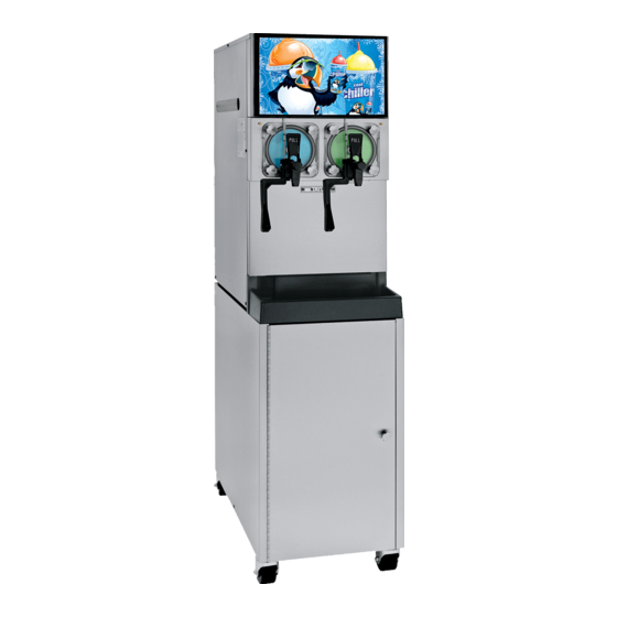
Slush freezer
Hide thumbs
Also See for C300:
- Original operating instructions (54 pages) ,
- Operating instructions manual (52 pages)

Related Manuals for Taylor C300


Summary of Contents for Taylor C300
- Page 1 OPERATOR’S MANUAL Model C300 Slush Freezer Original Operating Instructions 9/26/08 (Original Publication) 055072-M (Updated 1/8/2019)
- Page 2 Note: Only instructions originating from the factory or its authorized translation representative(s) are considered to be the original set of instructions. © 2006 Taylor Company 055072-M Any unauthorized reproduction, disclosure, or distribution of copies by any person of any portion of this work may be...
-
Page 3: Table Of Contents
Table of Contents Section 1: To the Installer Installer Safety ............1-1 Site Preparation . - Page 4 Table of Contents Section 6: Operating Procedures Assembly ............6-1 Sanitizing .
-
Page 5: Section 1: To The Installer
Failure to comply may result in ® of Taylor equipment. personal injury. • Only authorized Taylor service personnel should perform installation, maintenance, and repairs on Taylor equipment. For Indoor Use Only: This unit is designed to operate indoors, under normal ambient temperatures of •... -
Page 6: Water-Cooled Refrigeration Units
The authorized installer should inspect the unit for damage and promptly report any damage to the local authorized Taylor distributor. IMPORTANT! Install potable water connection with a water filter and adequate backflow protection to This unit is made using USA sizes of hardware. All metric comply with applicable national, state, and local codes. -
Page 7: Electrical Connections
If the supply cord is damaged, it must be on the unit. Check the data label(s) on the freezer for replaced by an authorized Taylor service branch circuit overcurrent protection or fuse, circuit technician in order to avoid a hazard. -
Page 8: Beater Rotation
Due to the types of products used in FCB equipment, it is systems. For information regarding applicable local laws, imperative that the freezing cylinder and the inlet tube be please contact your local authorized Taylor distributor. thoroughly brush cleaned, rinsed, and sanitized before running any product. -
Page 9: Section 2: To The Operator
The Model C300, when properly operated and cared for, will produce a consistent quality product. Like all mechanical products, this machine will require cleaning IMPORTANT! If the crossed-out wheeled-bin and scheduled maintenance. -
Page 10: Compressor Warranty Disclaimer
It should also be noted that Taylor does not warrant the refrigerant used in its equipment. For example, if the refrigerant is lost during the course of ordinary service... -
Page 11: Section 3: Safety
The installation location freezer and its parts. Taylor has gone to extreme efforts to is marked by the equipotential bonding symbol (5021 of... - Page 12 • If the supply cord is damaged, it must be knowledge and practical experience with the machine, in replaced by an authorized Taylor service particular as far as safety and hygiene are concerned. technician in order to avoid a hazard.
- Page 13 Noise Level: Airborne noise emission does not exceed 78 dB(A) when measured at a distance of 39 in. (1.0 m) from the surface of the machine and at a height of 62 in. (1.6 m) from the floor. Safety Model C300...
- Page 14 SAFETY Notes: Safety Model C300...
-
Page 15: Exploded View
Part No. Item Description Part No. Panel-Front-Lower 054670 Panel-Side-Left X54676- SER Shelf-Drip Tray 057938 Panel-Rear 054672 Tray-Drip 057738 Panel-Side-Right 054671 Shield-Splash 057939 Display-Lighted 069143 Switch-Rocker-OFF-ON 078418 Panel-Front-Upper 069142 Filter- Air- 15.88LX15.88H 052779- 5 Panel-Front-Shell 054668 Operator Parts Identification Model C300... -
Page 16: Beater Door Assembly
Shaft- Beater- Slush 083418 Plug- Prime- Slush 039568 Seal- Drive Shaft 032560 O-ring- 1.129 ODX.989ID X.070W O-ring- 7/8 OD X .139W 039219 025307 (25 to Bag) (25 to Bag) Nut- Spout- Door- Slush 039323 Operator Parts Identification Model C300... -
Page 17: Accessories
Brush-Draw Valve 1-1/2”OD 014753 Brush A.- Package X64275 Kit A.-Tune Up X39699 Brush-Mix Pump Body-3”x7” 023316 Lubricant-Taylor Hi Perf 048232 Brush-Double Ended 013072 Sanitizer-Stera Sheen See Note *Note: A sample container of sanitizer is sent with the unit. For Brush-Rear BRG 1”Dx2“L 013071 reorders, Order Stera Sheen part no. - Page 18 OPERATOR PARTS IDENTIFICATION Notes: Operator Parts Identification Model C300...
-
Page 19: Section 5: User Interface
When placed in the ON position, allows SLUSHTECH operation. SAFETY TIMEOUT ANY KEY ABORT Liquid Crystal Display The Liquid Crystal Display (LCD) is located on the front control panel. The LCD is used to show the current User Interface Model C300... -
Page 20: Operator Menu Display
(<- -) keys to move the cursor to the desired screen the display screens. Fault messages 2 and 3 indicate the selection and press the MENU (SEL) key. faults found in freezing cylinders 1 and 2 respectively. User Interface Model C300... - Page 21 L: H2O PRESSURE LOW R: H2O PRESSURE LOW THERMISTOR OPEN—One or both of the barrel + + + (freezing cylinder) thermistor probes are faulty. FAULT DESCRIPTION L: THERMISTOR OPEN R: NO FAULT FOUND + + + User Interface Model C300...
- Page 22 This screen allows the operator to manually defrost the left or right side of the unit. Place the cursor under YES, press the MENU (SEL) key, and the command will be executed. MANUAL DEFROST < > - User Interface Model C300...
- Page 23 The first feature indicates the software version. + + + - - - SYSTEM INFORMATION The fifth feature will indicate the left side defrost time and C300 CONTROL UVC2 which day(s) the defrost will occur. VERSION 1.03 DEFROST TIME LEFT CYCLE 1...
- Page 24 1. The fault description is listed on the Repeat for the right side of the unit. third line of the fault page. 10/25/06 <- - - -> + + + - - - User Interface Model C300...
-
Page 25: Syrup Out Indicator
This will continue until the CO is replaced. If the and spouts. is not replaced within 1-minute, the machine will shut down and a fault message will appear. User Interface Model C300... - Page 26 USER INTERFACE Notes: User Interface Model C300...
-
Page 27: Section 6: Operating Procedures
Operating Procedures Section 6 The Model C300 contains two 7 qt. (6.6 L) freezing Assembly cylinders. WARNING! Make sure the control switch is in WARNING! This unit is pressurized when in the OFF position to eliminate the chance of moving parts. - Page 28 3/8 in. inside the front of without binding. Remove any excess lubricant from the freezing cylinder. the seal. Important! Ensure the beater is properly seated. Failure to properly seat the beater may cause damage to the beater and the door. Operating Procedures Model C300...
- Page 29 11128 Figure 6-7 7. Before installing the draw valve, slide the two O-rings into the grooves on the draw valve. Lubricate the O- rings and the valve as illustrated below. 11126 Figure 6-10 Figure 6-8 Operating Procedures Model C300...
- Page 30 15. Place the two O-rings on the prime plug and lightly lubricate. 11193 Figure 6-12 12. Secure the assembly with the screw. 11445 Figure 6-16 16. Install the prime plug. Figure 6-13 13. Insert the spring into the front of the door spout. Operating Procedures Model C300...
-
Page 31: Sanitizing
Upon return to service, the unit must be sanitized prior to use. 1. Open the lighted display door. Place the control switch in the ON position. Operating Procedures Model C300... - Page 32 4. Connect the syrup line to the syrup line connector RINSE / SANITIZE that was cut from the syrup bag. < > - Press the MENU (SEL) key. Move the cursor under the word “SANITIZE” by pressing the OFF (<- -) key. Operating Procedures Model C300...
-
Page 33: Priming/Brixing
Press the OFF (<- - ) key. 11. Press the BEATER (- - -) key. Agitate the solution in the freezing cylinders for 5-minutes. Operating Procedures Model C300... - Page 34 6. Slowly move the syrup sampling valve to the fully open position by turning the handle “down” toward the sampling line. Allow the liquid to run into a pail until all the sanitizer is removed and full-strength product is flowing. Operating Procedures Model C300...
- Page 35 17. To place the freezing cylinders in the Auto mode, handle “up” to allow product to flow to the mix tank. press the AUTO (- ->) key on both sides. When the unit cycles off, the product will be at serving viscosity. Operating Procedures Model C300...
-
Page 36: 120 Day Closing Procedure
120 days. ALWAYS FOLLOW LOCAL HEALTH CODES. Figure 6-39 3. Repeat steps 1 and 2 for the other freezing cylinder. To disassemble the Model C300, the following items will be needed: • Two cleaning pails •... -
Page 37: Rinsing
Press the OFF (<- - ) key < > - 7. Press the BEATER (- - -) key to agitate the solution in 5. When draining is complete, press the OFF (<- -) key. each freezing cylinder for five minutes. Operating Procedures 6-11 Model C300... -
Page 38: Disassembly
• Hand screws • Freezer doors • Baffle assemblies • Beater assemblies and scraper blades • Drive shafts • Hopper covers • Front drip tray • Splash shield 6-12 Operating Procedures Model C300... - Page 39 Brush- clean all disassembled parts in the cleaning solution. Make sure all lubricant and syrup is removed. Place all the cleaned parts on a clean, dry surface to air- dry.. 5. Wipe clean all the exterior surfaces of the unit. Operating Procedures 6-13 Model C300...
- Page 40 OPERATING PROCEDURES Notes: 6-14 Operating Procedures Model C300...
-
Page 41: Section 7: Operator Checklist
Be sure there is a generous Your local Taylor distributor can perform this service for amount of cleaning solution on the brush. you. ... - Page 42 OPERATOR CHECKLIST Notes: Operator Checklist Model C300...
-
Page 43: Section 8: Troubleshooting Guide
Do not lubricate the hex end. If the rear shell shaft. necessary, contact a service bearing. technician for removal. 7. Excessive loss a. Leak in the CO system. a. Contact a service technician. - - - of CO Troubleshooting Guide Model C300... - Page 44 Wrong type lubricant on draw b. Use food grade lubricant valve O-rings. (example: Taylor Lube HP). c. Worn or missing draw valve O- c. Replace or install O-rings on 6-3 / 9-1 rings. draw valve.
-
Page 45: Section 9: Parts Replacement Schedule
Black Bristle Brush, 1” x 2” Inspect and replace if necessary. Minimum Double-Ended Brush Inspect and replace if necessary. Minimum Brush, 1-1/2” x 2” Inspect and replace if necessary. Minimum Brush, 3” x 7” Inspect and replace if necessary. Minimum Parts Replacement Schedule Model C300... - Page 46 PARTS REPLACEMENT SCHEDULE Notes: Parts Replacement Schedule Model C300...
-
Page 47: Section 10: Limited Warranty On Equipment
LIMITED WARRANTY Taylor warrants the Product against failure due to defect in materials or workmanship under normal use and service as follows. All warranty periods begin on the date of original Product installation. If a part fails due to defect during the applicable warranty period, Taylor, through an authorized Taylor distributor or service agency, will provide a new or re-manufactured part, at Taylor’s option, to replace the failed defective part at no charge for the part. - Page 48 LEGAL REMEDIES The owner must notify Taylor in writing, by certified or registered letter to the following address, of any defect or complaint with the Product, stating the defect or complaint and a specific request for repair, replacement, or other correction of the Product under warranty, mailed at least thirty (30) days before pursuing any legal rights or remedies.
-
Page 49: Section 11: Limited Warranty On Parts
Taylor warrants the Parts against failure due to defect in materials or workmanship under normal use and service as follows. All warranty periods begin on the date of original installation of the Part in the Taylor unit. If a Part fails due to defect during the applicable warranty period, Taylor, through an authorized Taylor distributor or service agency, will provide a new or re-manufactured Part, at Taylor’s option, to replace the failed defective Part at no charge for the Part. - Page 50 Taylor. 5. Replacement of wear items designated as Class “000” Parts in the Taylor Operator’s Manual, as well as any release sheets and clips for the Product’s upper platen assembly.
- Page 51 LEGAL REMEDIES The owner must notify Taylor in writing, by certified or registered letter to the following address, of any defect or complaint with the Part, stating the defect or complaint and a specific request for repair, replacement, or other correction of the Part under warranty, mailed at least thirty (30) days before pursuing any legal rights or remedies.
- Page 52 LIMITED WARRANTY ON PARTS Notes: 11-4 Limited Warranty on Parts Model C300...
Need help?
Do you have a question about the C300 and is the answer not in the manual?
Questions and answers