
Related Manuals for Taylor 349


Summary of Contents for Taylor 349
- Page 1 OPERATOR’S MANUAL Model 345/346/349/355 Slush Freezers Original Operating Instructions 039710- M 6/19/01 (Original Publication) Updated 4/16/15...
-
Page 2: Model
Complete this page for quick reference when service is required: Taylor Distributor: Address: Phone: Fax: E- mail: Service: Parts: Date of Installation: Information found on the data label: Model Number: Serial Number: Electrical Specs: Voltage Cycle Phase Maximum Fuse Size: Minimum Wire Ampacity: E 2001 Carrier Commercial Refrigeration, Inc. -
Page 3: Table Of Contents
............Table of Contents Models 345, 346, 349, 355... - Page 4 Statutory Damages of up to $250,000 (17 USC 504) for infringement, and may result in further civil and criminal penalties. All rights reserved. Taylor Company a division of Carrier Commercial Refrigeration, Inc. 750 N. Blackhawk Blvd. Rockton, IL 61072 Models 345, 346, 349, 355 Table of Contents...
-
Page 5: To The Installer
This piece of equipment is made in the USA and has Note: All repairs must be performed by an USA sizes of hardware. All metric conversions are authorized Taylor Service Technician. approximate and vary in size. 131122 Models 345, 346, 349, 355 To the Installer... -
Page 6: Water Cooled Refrigeration Units (Water Cooled Units Only)
Refer to improve the quality of the water and to avoid the wiring diagram provided inside of the control box clogging the operating components. for proper power connections. 120828 To the Installer Models 345, 346, 349, 355... - Page 7 GFI, to protect against the leakage of current, installed by the authorized personnel to the local codes. In consideration of our environment, Taylor uses only earth friendly HFC refrigerants. The HFC refrigerant used in this unit is R404A. This refrigerant...
-
Page 8: Syrup System Connections
If burns are severe, apply freezer. ice packs and contact a physician immediately. Taylor reminds technicians to be cautious of government laws regarding refrigerant recovery, recycling, and reclaiming systems. If you have any questions regarding these laws, please contact the factory Service Department. - Page 9 CO tank. Watch the high pressure gauge; it should hold pressure. If it does not, there is a CO leak. Use a soap solution to locate and repair the Figure 5 leak. Models 345, 346, 349, 355 To the Installer...
- Page 10 You should always stay within the 20 to 25 PSI range as the gauge reflects the pressure in the hopper and barrel. The setting will be determined by the desired overrun and the syrup used. To the Installer Models 345, 346, 349, 355...
-
Page 11: To The Operator
Taylor compressor warranty. It is the unit owner’s responsibility to make Note: Your Taylor warranty is valid only if the parts are this fact known to any technician he employs. authorized Taylor parts, purchased from the local... -
Page 12: Safety
Section 3 Safety We at Taylor are concerned about the safety of the operator when he or she comes in contact with the freezer and its parts. Taylor has gone to extreme efforts to design and manufacture built- in safety DO NOT operate the freezer unless it is features to protect both you and the service technician. - Page 13 78 dB(A) when measured at a distance of 1.0 experience with the unit, in particular as far as safety meter from the surface of the machine and at a height and hygiene are concerned. of 1.6 meters from the floor. 131122 Models 345, 346, 349, 355 Safety...
-
Page 14: Operator Parts Identification
Lock-Caster Bracket 032571 Panel-Front-Upper 043600-BLA Shield-Splash 043719 Plate A.-Dec-345-346-355 Black 043639-BLA Tray-Drip *345/6* Black w/Drain 043720-SP Decal- Dec- Taylor Domed 053761 Pan-Drip 19-1/2 Long 035034 Pan-Drip (White) For Drip Guide 043612 *Not Shown Operator Parts Identification Models 345, 346, 349, 355... -
Page 15: Model 346
Filter- Air 18L x 16.5H x .70W AC 052779- 1 Pan-Drip 19-1/2 Long 035034 Cover- Hole- Filter- Snap In 053801 Panel-Service *346* Filter 053612 Pan-Drip (White) For Drip Guide 043612 *Not Shown Models 345, 346, 349, 355 Operator Parts Identification... -
Page 16: Model 349
Filter- Air 18 L x 16.5 H x .7 W 052779- 1 Tray-Drip (Black) w/Drain 038275-SP Pan A.-Drip w/Hose Left X42201 Shield-Splash 038276 Pan A.-Drip w/Hose Right X42203 Panel-Front-Lower 042082-BLA *Not Shown Operator Parts Identification Models 345, 346, 349, 355... -
Page 17: Model 355
Leg-4” 3/8-16 Stud 036397 Card-FCB POP 043957 Shelf-Drip Tray 049697 Plate-Dec-345-346-355 Black 043639-BLA Tray-Drip 20” L x 8” D x 3-3/4 043720 Pan-Drip (White) For Drip Guide 043612 Shield-Splash 043719 *Not Shown Models 345, 346, 349, 355 Operator Parts Identification... -
Page 18: Door Assembly
*NOTE: O-RING 025307 IS NOT USED ON ALL MODELS. HOWEVER, UNITS BUILT PRIOR TO 10/2009 THAT HAVE NOT BEEN UPDATED WITH METAL REAR SHELL BEARING X67222 OR X83989 STILL REQUIRE O-RING. 150415 Operator Parts Identification Models 345, 346, 349, 355... -
Page 19: Accessories
*Note: A sample container of sanitizer is sent with the unit. For reorders, order Stera Sheen part no. 055492 (100 2 oz. packs) or Kay- 5 part no. 041082 (200 packs). 150112 Models 345, 346, 349, 355 Operator Parts Identification... -
Page 20: Important: To The Operator
The control switch is located on the top of the control symbols to indicate their functions. The Model 349 is channel. When placed in the ON position, allows designed with these International symbols. -
Page 21: Liquid Crystal Display
Conditions, the display will return to the system mode screen 60 seconds after the last keypress. The Current Conditions screen will be displayed until Note: Syrup, CO and water are satisfied. manually changed. Models 345, 346, 349, 355 Important: To the Operator... - Page 22 + + + there is more than one fault, press the +++ key. Note: On a Model 349, faults for freezing cylinders 1 and 2 are shown on the first screen. Press the SEL key THERMISTOR OPEN - One or both of the to read fault messages for freezing cylinders 3 and 4.
- Page 23 OPERATOR MENU, press the SEL key once. To + + + return to the Main Screen, use the right arrow key to cycle to MENU ITEM A, then press the SEL key. Models 345, 346, 349, 355 Important: To the Operator...
- Page 24 - - - freezing cylinder to be defrosted at a time. This applies to freezing cylinder pairs on the model 349. Attempting This screen will appear if an invalid date is entered. to place a freezing cylinder into defrost while the other...
- Page 25 +++ or - - - keys to access the other days of the week. If a Power Saver Mode is programmed, one of the following screens will appear. (The model 349 will DEFROST TIME LEFT display defrost information for freezing cylinders 1, 2,...
-
Page 26: Syrup Out Indicator
40 F/4.4 letter “A”, and press the MENU/SEL key. The following screen is exemplary of models 345, 346, and 355. The model 349 displays all four freezing OPERATOR MENU cylinders. A B C D E F G H SERVICE MENU <- - - - - - >... -
Page 27: Co2 Out Indicator
Remove the splash shield, front drip tray and center the machine will shut down and a fault message will drip pan. Take these parts to the sink and brush-clean appear. them. Re-install the parts onto the freezer. Models 345, 346, 349, 355 Important: To the Operator... -
Page 28: Operating Procedures
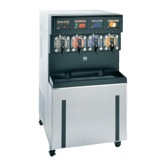
Operating Procedures Assembly The Models 345, 346 and 355 contain two 7 quart (6.6 liter) freezing cylinders. The Model 349 contains four 7 quart (6.6 liter) freezing cylinders. MAKE SURE THE CONTROL SWITCH IS IN THE OFF POSITION. Failure to do so may result in CAUTION: This unit is pressurized when personal injury or component damage. - Page 29 3/8” inside the front of the binding. Remove any excess lubricant from the seal. freezing cylinder. Important: Failure to properly seat the beater may cause damage to the beater and the door. Figure 12 Figure 14 Models 345, 346, 349, 355 Operating Procedures...
- Page 30 Insert the draw valve into the freezer door spout from the front of the unit. The valve is properly installed when the hole in the draw valve is visible in the slot of the freezer door spout. Figure 19 Operating Procedures Models 345, 346, 349, 355...
- Page 31 Place the threaded cap on the end of the draw valve cavity. Turn the cap clockwise until it is secure. Figure 24 Note: Every three months, discard the o-rings and Figure 22 install new o-rings. Models 345, 346, 349, 355 Operating Procedures...
- Page 32 Position the open end of the vinyl tube into the rear drip pan. Figure 26 Figure 29 Step 8 Repeat Steps 1 through 8 for the remaining freezing Place the o-ring into the groove of the hopper cover. cylinder(s). Operating Procedures Models 345, 346, 349, 355...
-
Page 33: Sanitizing
Connect the syrup line to the syrup connection that the side panels to gain access to the hoppers. Place was cut from the syrup bag. the control switch in the ON position. Figure 31 Figure 33 Models 345, 346, 349, 355 Operating Procedures... - Page 34 PPM sanitizing solution (example: Kay-5 ). USE Press the PRIME key. This will cause the sanitizing solution to flow through the lines and into the mix WARM WATER AND FOLLOW THE MANUFACTUR- hopper. ER’S SPECIFICATIONS. 140813 Operating Procedures Models 345, 346, 349, 355...
- Page 35 CO fitting and mix feed tube. Use caution when cleaning the float switch so as not to damage it. Figure 41 Figure 39 Figure 42 Models 345, 346, 349, 355 Operating Procedures...
- Page 36 Disconnect the syrup connector in the sanitizing solution. Repeat Steps 2 through 14 for the remaining freezing cylinder(s). Step 17 Remove the right side panel and install the rear white Figure 45 drip pan. Operating Procedures Models 345, 346, 349, 355...
-
Page 37: Priming/Brixing
Brix is the ratio of syrup to water which will directly affect the quality and taste of the product. Brixing should be done before priming the freezer and when Figure 49 a change in syrup flavor has been made. Models 345, 346, 349, 355 Operating Procedures... - Page 38 Once the proper brix has been achieved, close the sampling valve. Install the front drip tray and the splash Repeat this step for the remaining freezing shield on the front of the freezer. cylinder(s). Operating Procedures Models 345, 346, 349, 355...
-
Page 39: 90 Day Closing Procedure
Slowly open the sampling valve and allow cleaner to flow through this line and out into the pail. After approximately 1/2 gallon of cleaner has been Figure 56 dispensed, close the valve. 140813 Models 345, 346, 349, 355 Operating Procedures... -
Page 40: Disassembly
Step 13 Disconnect the syrup connector. Figure 58 Step 3 Remove the rear drip pan. (Does not apply to the Repeat Steps 2 through 13 for the remaining freezing cylinder(s). Model 349.) Operating Procedures Models 345, 346, 349, 355... - Page 41 Place all the cleaned parts on a clean, dry freezer doors, o-rings from mix hopper covers. surface to air-dry. Step 7 Discard all o-rings and replace them with new ones. Wipe clean all the exterior surfaces of the freezer. Models 345, 346, 349, 355 Operating Procedures...
-
Page 42: Important: Operator Checklist
Too strong of a solution may damage expose condenser(s). Never the parts and too weak of a solution will not do screwdrivers or other metal probes to clean an adequate job of cleaning or sanitizing. between the fins. Important: Operator Checklist Models 345, 346, 349, 355... -
Page 43: Winter Storage
Note: It is recommended that an authorized service technician perform winter storage draining, to insure Your local Taylor Distributor can perform this service all water has been removed. This will guard against for you. freezing and rupturing of the components. -
Page 44: Troubleshooting Guide
Contact a service - - - technician. bound in the COLD position. c. Condenser dirty, A/C. c. Clean condenser monthly. d. Water supply off, W/C. d. Turn the water on. - - - Troubleshooting Guide Models 345, 346, 349, 355... - Page 45 13. Carbonated water or a. Faulty check valve in a. Call a service technician - - - to replace the check sulfuric aroma is evident carbonation system. valve. in the faucet or sewage system. Models 345, 346, 349, 355 Troubleshooting Guide...
-
Page 46: Parts Replacement Schedule
Double Ended Brush Inspect & Replace if Minimum Necessary White Bristle Brush, 1-1/2” x 2” Inspect & Replace if Minimum Necessary White Bristle Brush, 3” x 7” Inspect & Replace if Minimum Necessary Parts Replacement Schedule Models 345, 346, 349, 355... -
Page 47: Section 10 Limited Warranty On Equipment
Taylor, through an authorized Taylor distributor or service agency, will provide a new or re- manufactured part, at Taylor’s option, to replace the failed defective part at no charge for the part. Except as otherwise stated herein, these are Taylor’s exclusive obligations under this limited warranty for a Product failure. - Page 48 LEGAL REMEDIES The owner must notify Taylor in writing, by certified or registered letter to the following address, of any defect or complaint with the Product, stating the defect or complaint and a specific request for repair, replacement, or other correction of the Product under warranty, mailed at least thirty (30) days before pursuing any legal rights or remedies.
-
Page 49: Limited Warranty On Parts
Taylor warrants the Parts against failure due to defect in materials or workmanship under normal use and service as follows. All warranty periods begin on the date of original installation of the Part in the Taylor unit. If a Part fails due to defect during the applicable warranty period, Taylor, through an authorized Taylor distributor or service agency, will provide a new or re- manufactured Part, at Taylor’s option, to replace the failed defective Part at no... - Page 50 Parts or the units in which they are installed repaired or altered in any way so as, in the judgment of Taylor, to adversely affect performance, or normal wear or deterioration.
-
Page 51: Taylor Company
LEGAL REMEDIES The owner must notify Taylor in writing, by certified or registered letter to the following address, of any defect or complaint with the Part, stating the defect or complaint and a specific request for repair, replacement, or other correction of the Part under warranty, mailed at least thirty (30) days before pursuing any legal rights or remedies.
Need help?
Do you have a question about the 349 and is the answer not in the manual?
Questions and answers