
Subscribe to Our Youtube Channel
Related Manuals for Chauvin Arnoux Metrix DOX2025B


Summary of Contents for Chauvin Arnoux Metrix DOX2025B
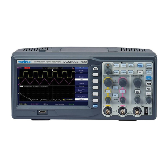
- Page 1 Digital oscilloscopes DOX2025B Two channels - 25MHz - 500MSP/s DOX2070B Two channels - 70MHz - 1GSP/s DOX2100B Two channels - 100MHz - 1GSP/s User’s manual X03985B02 - Ed. 01 - 06/17...
-
Page 2: Table Of Contents
Contents Contents General instructions ................Introduction ........Precautions and safety measurements ......... Symbols marked on the instrument ........... Warranty, Servicing, Maintenance Description of the instrument ................Front panel ..................Back ..............Display interface ........Menu and command buttons and keys ................ - Page 3 Sommaire Contents (cont’d) ......................V - DISPLAY system ........... Configuration of the display ................X-Y format ....................VI - MEASUREMENT system ............... Scale measurement ............Measurements by cursors ......1. Manual cursor ......2. Track mode ......3. Auto mode ............
- Page 4 General instructions General instructions You have just acquired a two-channel digital oscilloscope: Introduction DOX2025B, 25 MHz, 500 MSP/s DOX2070B 70 MHz, 1 GSP/s DOX2100B, 100 MHz, 1 GSP/s Your oscilloscope has functions for applications in production, education, maintenance, services, and research and development.
-
Page 5: Symbols Marked On The Instrument
General instructions General instructions (cont'd) Symbols marked Warning, risk of danger. Refer to the operating instructions for information about the nature of on the instrument the potential danger and the actions to be taken to avoid such dangers. Sorting of wastes for the recycling of electrical and electronic equipment. -
Page 6: Description Of The Instrument Front Panel
Description of the instrument Description of the instrument Front panel Menu Adjust keys Horizontal Common knob ON/OFF key Start/Stop controls functions Menu controls AUTO-SET Trigger Controls Vertical Print controls Input Calibration key in BMP terminals signal Host extension on USB key only Back INPUT... -
Page 7: Display Interface
Description of the instrument Description of the instrument (cont'd) Display interface 8 9 10 Trigger status: Set: The oscilloscope is in pre-trigger data acquisition. All triggers are ignored in this status. Ready: All pre-trigger data have been acquired and the oscilloscope is ready to accept a trigger. -
Page 8: Menu And Command Buttons And Keys
Description of the instrument Description of the instrument (cont'd) Menu and command buttons and keys Channel keys (CH1, Press one of the channel keys, CH1 or CH2, to activate it (ON) or deactivate CH2) it (OFF) and access the menu used to configure the channel. When the channel is active, the corresponding channel button is lit. -
Page 9: Adjust Knob
Description of the instrument Description of the instrument (cont'd) ACQUIRE Displays the Acquisition menu. You can use the Acquisition menu to parameterize the Sampling mode (sample, peak detection, mean). MEASURE Displays the Measurement menu. CURSORS Displays the Cursor menu. The "Adjust" knob is used to set the position of the active cursor. -
Page 10: Getting Started Check Of Operation
Getting started Getting started Check of In order to check the proper operation of the oscilloscope, perform the operation following operations: Steps 1. Power up the oscilloscope. Press "Default Setup" to load the default configuration of the oscilloscope. The default attenuation of the probe is 1X. 2. - Page 11 Getting started Getting started (cont'd) Probe A guard around the probe body protects your fingers from electric shocks. Connect the probe to the oscilloscope, then connect the crocodile clip of the earthing cable of the probe to the earth reference potential of the circuit to be tested before making a measurement.
- Page 12 Getting started Getting started (cont'd) Compensation Method used to compensate the probe (in the X10 position) manually to of the probe couple it to the input channel: Steps 1. Set the probe factor in the channel CH1 menu to 10X. Set the switch of the probe to 10X and connect the probe to channel CH1 of the oscilloscope.
-
Page 13: Autoset
Functional description Functional description AUTOSET AUTOSET The DOX2000B digital oscilloscope has an "AUTOSET" function that is used to automatically configure the device to produce a display appropriate to the signals present on the inputs. After starting an AUTOSET, if necessary, select the desired signal waveform from among the 4 available: Autoset Option... -
Page 14: Factory Configuration
Functional description Functional description AUTOSET (cont'd) Autoset Function menu Values function Acquisition Sample mode Display format Dots for a video signal; Vectors for an FFT spectrum; Type of display otherwise unchanged Vertical DC or AC depending on the input signal coupling Bandwidth limit Bandwidth limiter inactive (full band) -
Page 15: I - Vertical System
Functional description Functional description I - VERTICAL System The buttons, knobs, and keys of the vertical keypad are used to display the signals and to adjust the vertical sensitivity and position. CH2 Volt/div knob CH1 Volt/div knob MATH Key CH1 key CH2 key REF key CH2 vertical... - Page 16 Functional description Functional description I - VERTICAL system (cont'd) Configuration of Each channel has its own menu. channels CH1, CH2 ● Pressing "CH1"→"Coupling"→"AC" selects AC input coupling. 1. Selection of the input coupling The DC component of the signal is blocked. ●...
- Page 17 Functional description Functional description I - VERTICAL system (cont'd) 3. Adjustment of the The vertical scale can be adjusted in Coarse and Fine mode; the vertical vertical sensitivity sensitivity band is from 2mV/div to 10V/div. For example, for CH1: ● Pressing "CH1"→"Volts/ Div"→ "Coarse" Volts/div, the default value. The vertical sensitivity can be adjusted in hops in a 1-2-5 staging from 2mV/div, 5mV/div, and 10mV/div up to 10V/div.
- Page 18 Functional description Functional description I - VERTICAL system (cont'd) 5. Invert the For example, on CH1: signals ● Press "CH1"→ "Next Page" "page 1/3" →"Invert" → "On": 6. Using the digital ● Press "CH1" → "Next Page page 1/3" → "Filter", to access the Digital Filter filter menu.
-
Page 19: Buttons Of The Vertical Mode
Functional description Functional description I - VERTICAL system (cont'd) 2. Buttons of the vertical mode Vertical position 1. Use the "Vertical position" knobs to move the traces up or down on the knobs screen. 2. While you adjust the vertical position of the trace, the value "Volts Pos = " is displayed at bottom left on the screen. -
Page 20: Mathematics Functions
Functional description Functional description I - VERTICAL system / MATHematics function 4. MATH menu MATH displays the results of +, -, *, /, and FFT operations on channels CH1 and CH2. Press the MATH key to access the MATHematics menu. Menu Function Values... -
Page 21: Fft Process
Functional description Functional description I - VERTICAL System / MATHematics function (cont'd) The FFT process mathematically converts a signal in the time domain 1) FFT process into its components in the frequency domain. It is possible to measure the amplitude and frequency of the spectral components. FFT function FFT option Values... - Page 22 Functional description Functional description I - VERTICAL system / MATHematics function (cont'd) 2) Display of the Press the MATH button to display the Math menu. Use the options to select FFT spectrum the Source channel, the Window, and the FFT Zoom factor. Only one FFT can be displayed at a time.
- Page 23 Functional description Functional description I - VERTICAL system / MATHematics function (cont'd) 4) Zoom and You can use the zoom and the cursors to select measurements positioning of the FFT spectrum. The oscilloscope has an "FFT Zoom" option to effect a of an FFT spectrum horizontal zoom;...
- Page 24 Functional description Functional description I - VERTICAL system / MATHematics function (cont'd) Frequency 1. Press the CURSOR button 2. Press the "Cursor Mode" button and choose "Manual". 3. Press "Type" and choose "Time". 4. Press "Source" and choose "MATH". 5. Press "CurA", turn the "Adjust" knob to place Cursor A on the spectral component having the highest amplitude.
-
Page 25: Ii - Horizontal System
Functional description Functional description II - HORIZONTAL system HORIZONTAL menu The "HORIZONTAL" keypad contains one key and two knobs. S/div knob Horizontal menu Horizontal position knob Horizontal menu Option Values Description Delayed Activate this function to simultaneously display the signal according to the main time base at the top of the screen and according to the delayed time base at the bottom of the screen. -
Page 26: Horizontal Mode
Functional description Functional description II - HORIZONTAL system (cont'd) Buttons of the horizontal mode The horizontal commands serve to adjust the sweep coefficient and the horizontal position of the traces. 1. Adjusts the horizontal position of the traces (the position of the trigger Horizontal with respect to the centre of the screen). -
Page 27: Iii - Trigger System
Functional description Functional description III - TRIGGER system TRIGGER mode The trigger symbol T indicates the instant at which the triggering event (Trigger) occurred. The DOX2000 oscilloscopes have five types of trigger: Edge, Video, Pulse, Slope, Alternate Trig menu key Set to 50% key Force Trig key LEVEL knob... -
Page 28: Edge
Functional description Functional description III - TRIGGER system (cont'd) 1. EDGE Option Values Description Edge Trigger Type Edge The rising or falling edge of the source signal is used for Menu triggering. Source The triggering source is active whether or not the channel is displayed. - Page 29 Functional description Functional description III - TRIGGER system (cont'd) Steps 1. Configure the type 1) Press the "TRIG MENU" key to display the "Trigger" menu. 2) Press the "Type" option key and choose "Edge". 2. Configure the Triggering source To select the source, press the "Source" button to choose "CH1", "CH2", "EXT", "EXT/5", or "AC Line".
-
Page 30: Pulse
Functional description Functional description III - TRIGGER system (cont'd) 2. PULSE Use the pulse width to trigger on abnormal pulses. Pulse trigger Option Values Description page 1 Type Pulse Select the type and width of the triggering pulse. Source Choose the triggering source. - Page 31 Functional description Functional description III - TRIGGER system (cont'd) Pulse trigger, Option Values Description page 2 Type Pulse Selection of the pulse corresponding to the triggering condition. Auto Mode Choose the type of triggering. The normal Normal mode is suitable for most applications of Single triggering on pulse width.
-
Page 32: Video
Functional description Functional description III - TRIGGER system (cont'd) 3. VIDEO triggering To trigger on the fields or the lines of standard video signals. Video trigger Option Values Instructions Type Video To choose the type of video, choose AC page 1 coupling;... - Page 33 Functional description Functional description III - TRIGGER system (cont'd) Steps 1. Configure the type 1) Press the "TRIG MENU" key to display the "Trigger" menu. 2) Press the "Type" key and choose "Video" 2. Configure the polarity Press the "Polarity" option key to choose "", " "...
-
Page 34: Slope
Functional description Functional description III - TRIGGER system (cont'd) 4. SLOPE Triggering on a positive or negative slope according to the configuration. Trigger on Slope Option Values Instruction page 1 Type Slope Triggering on the duration of the positive or negative slope. Source Choose the triggering source. - Page 35 Functional description Functional description III - TRIGGER system (cont'd) Trigger on Slope Option Values Instruction Type Slope Triggering on the positive or negative page 2 slope Vertical Choose the triggering level to be adjusted by the "LEVEL" knob. You can adjust "LEVEL A", "LEVEL B", or both at once.
-
Page 36: Alternate
Functional description Functional description III - TRIGGER system (cont'd) ALTERNATE triggering When you use alternate triggering the triggering source is alternately channel CH1 and channel CH2. With this mode, you can observer two asynchronous signals at the same time. You can choose different types of trigger for two vertical signals. - Page 37 Functional description Functional description III - TRIGGER system (cont'd) Trigger on Pulse Option Values Instructions page 1 Type In this mode, the triggering source comes alternately from channels CH1 and CH2. This Alternate mode is used to observe asynchronous signals. Configure triggering source CH1 Source Configure triggering source CH2...
- Page 38 Functional description Functional description III - TRIGGER system (cont'd) Trigger on Video Option Values Instructions page 1 Type Alternate The triggering source comes alternately from channels CH1 and CH2. This mode is used to observe asynchronous signals. Source Configure triggering source CH1 Configure triggering source CH2 Choose Video as type of triggering.
- Page 39 Functional description Functional description III - TRIGGER system (cont'd) Trigger on Slope Option Values Instructions page 1 Type Alternate The triggering source comes alternately from channels CH1 and CH2. This mode is used to observe asynchronous signals. Configure triggering source CH1 Source Configure triggering source CH2 Mode...
- Page 40 Functional description Functional description III - TRIGGER system (cont'd) Steps To obtain a stable display in the case of two asynchronous signals, follow the instructions below: Inject asynchronous signals on channels CH1 and CH2. Press the "AUTO" key. Press the "TRIG MENU" key to access the "Trigger Menu". Press the "Type"...
- Page 41 Functional description Functional description III - TRIGGER system (cont'd) COUPLING Use the coupling appropriate to the triggering source signal. To choose the coupling of the trigger, first press the "TRIG MENU" key to choose the triggering mode - "edge", "pulse", video" or "slope" -, then choose in the "Set Up"...
- Page 42 Functional description Functional description III - TRIGGER system (cont'd) HOLD-OFF Use Hold-Off to obtain a stable display with complex signals, such as pulse trains, for example. The Hold-Off time is the time interval between the detection of a valid triggering event and the time when the oscilloscope is ready to detect another triggering event.
-
Page 43: Iv - Acquisition System
Functional description Functional description IV - ACQUISITION system Acquisition menu During the acquisition of a signal, the oscilloscope converts it to digital format and displays a trace. The acquisition mode determines how the signal is digitized. The time base range determines the duration of recording and the elementary acquisition pitch. - Page 44 Functional description Functional description IV - ACQUISITION system (cont'd) Sample The oscilloscope samples the signal at regular intervals to construct the trace. In general, this mode gives an accurate representation of the signal. Advantage You can use this mode to reduce random noise. Disadvantages The "sample"...
- Page 45 Functional description Functional description IV - ACQUISITION system (cont'd) Averaging The oscilloscope performs several acquisitions, determines the mean, and displays the resulting trace. Advantage You can use this mode to reduce random noise. Mode Equivalent time The equivalent time sampling (ETS) mode can reach a horizontal resolution sampling of 20ps (equivalent to 50GSa/s).
-
Page 46: Time Base
Functional description Functional description IV - ACQUISITION system (cont'd) Time base The oscilloscope digitizes the traces through the acquisition of an input signal at precise points. The time base is used to control the trace sampling rate. Use the "S/div" knob to adjust the time base coefficient scale that suits you. Undersampling Aliasing occurs when the sampling rate of the oscilloscope is not fast enough to reconstruct a trace precisely. - Page 47 Functional description Functional description IV - ACQUISITION system (cont'd) "X" corresponds to "linear" interpolation: Configure the Sampling mode Press the "Mode" key and choose "Real Time" (Real Time Sampling, RTS) or "Equivalent Time" (Equivalent Time Sampling, ETS). Sampling rate Adjust the time base coefficient by turning the "T/div" knob of the HORIZONTAL keypad;...
-
Page 48: Run Control Run/Stop, Single
Functional description Functional description IV - ACQUISITION system (cont'd) Run control Run/Stop Press the "RUN/STOP" key to start (RUN) the continuous acquisition of signals. Press this key again to stop the acquisition. Single Press the "SINGLE" button to select the "Single" mode. In "SINGLE"... -
Page 49: Display System
Functional description Functional description V - DISPLAY system Configuration of Press the "DISPLAY" key. the display Display Option Values Description Type Vectors "Vectors": joins two adjacent samples by a page 1 line segment. Dots: displays all points acquired. Dots Persistence Defines how long the display of the samples 1 sec acquired is held. - Page 50 Functional description Functional description V - DISPLAY system (cont'd) Display Option Values Instructions page 2 The YT format displays the voltage (vertical scale) vs time (horizontal scale). Format The XY format displays a dot for each couple of samples acquired simultaneously in channels CH1 = X and CH2 = Y.
- Page 51 Functional description Functional description V - DISPLAY system (cont'd) Display Option Values Instructions page 3 Interface Classical Configure the display style. Modern Traditional Simple Next page Page 3/3 Press this button to return to the first page. Steps 1. Configure the type of display 1) Press the "DISPLAY"...
- Page 52 Functional description Functional description V - DISPLAY system (cont'd) X-Y format The XY format is used to analyse phase differences between signals using Lissajous figures. The XY format plots the voltage in channel CH1 (horizontal X axis) against the voltage in channel CH2 (vertical Y axis). The oscilloscope uses the triggerless acquisition mode and displays the data in the form of dots.
-
Page 53: Measurement System
Functional description Functional description VI - MEASUREMENT system The oscilloscope displays waveforms, in other words variations of the signal amplitude (voltage) as a function of time. The oscilloscope also displays the vertical and horizontal ranges and the results of cursor and automatic measurements. Scale measurement This method allows a rapid visual estimate. - Page 54 Functional description Functional description VI - MEASUREMENT system (cont'd) Steps 1. Press the "CURSORS" key to display the measurement by cursors menu. 2. Press the "Mode" key and choose "Manual". 3. Press the "Type" key and choose "Voltage" or "Time". 4.
- Page 55 Functional description Functional description VI - MEASUREMENT system (cont'd) Steps 1. Press the "CURSOR" key to display the cursor menu. 2. Press the "Mode" key and choose "Track". 3. Press the "Cursor A" key to choose the attached channel. 4. Press the "Cursor B" key to choose the attached channel. 5.
- Page 56 Functional description Functional description VI - MEASUREMENT system (cont'd) 3. Auto mode This mode makes automatic measurements. Option Values Description Cursor mode Auto Configures the cursor mode. Steps 1. Press the "CURSORS" key to display the "Cursor Measurement" menu. 2. Press the "Cursor Mode" key and choose "Auto". 3.
-
Page 57: Time Measurements
Functional description Functional description VI - MEASUREMENT system (cont'd) Automatic Press the "MEASURE" key to open the Automatic measurements menu: measurements Three types of automatic measurement are available: Voltage measurement Time measurement Delay measurement 32 measurement parameters are available. Automatic Option Instructions... - Page 58 Functional description Functional description VI - MEASUREMENT system (cont'd) 1. Automatic Option Values Instructions VOLTAGE Source CH1 CH2 Choose the reference Measurements channel for the Voltage measurements. Type Vmax, Vmin, Vpp, Vamp, Press the "Type" key or turn Vtop, Vbase, Cycle Mean, the "Adjust"...
- Page 59 Functional description Functional description VI - MEASUREMENT system (cont'd) 3. Automatic DELAY Option Values Instructions Measurements Source CH1-CH2 Reference channels for the delay measurement. Type Phase FRR FRF FFR FFF Press the "Type" key or turn the LRR LRF LFR LFF "Adjust"...
- Page 60 Functional description Functional description VI - MEASUREMENT system (cont'd) Types of Types of Description measurement measurement The maximum positive peak of the signal. Vmax The minimum negative peak of the signal. Vmin Absolute difference between the maximum and minimum peaks of the signal. Value of the high plateau of the signal.
- Page 61 Functional description Functional description VI - MEASUREMENT system (cont'd) Steps Voltage measurements 1. Press the "MEASURE" key to display the "Automatic Measurements" menu. 2. Press the first key at the bottom to access the "second measurement menu". 3. Choose the type of measurement. If you press the "Voltage" key, the "Voltage measurement"...
- Page 62 Functional description Functional description VI - MEASUREMENT system (cont'd) Steps Time measurement 1. Press the "MEASURE" key to display the "Automatic Measurements" menu. 2. Press the bottom key to access the second page of the Automatic measurements menu. 3. Press the "All" key to access the "All measurements" menu. 4.
-
Page 63: Storage System
Functional description Functional description VII - STORAGE system SAVE The "SAVE/RECALL" key corresponds to the Storage function. 5 types of data: - Set-up Parameters - Curve - Image - CSV Factory You can save in internal memory and retrieve on screen up to 20 configurations of the oscilloscope and 20 traces. - Page 64 Functional description Functional description VII - STORAGE system (cont’d) 1.1 Recall of files The "Load" key can be used to restore your configuration files. When you have selected the file in question and it is highlighted in the main zone of the screen, press the "Load"...
-
Page 65: Save/Recall Of The Configuration
Functional description Functional description VII - STORAGE system (cont'd) 2. Save and Recall of the configuration The whole configuration is stored in non-volatile memory. When you restore the configuration, the oscilloscope will be in the mode from which the configuration was saved. The oscilloscope saves the current configuration if you wait three seconds after the last change before powering it down. - Page 66 Functional description Functional description VII - STORAGE system (cont'd) Save Example: Save the configuration corresponding to a "Dots" type display in the steps internal memory of the oscilloscope. 1. Press the "SAVE/RECALL" key to display the "SAVE/RECALL" menu. 2. Press the "Type" key and choose "Set-ups". 3.
- Page 67 Functional description Functional description VII - STORAGE system (cont'd) Save steps Save the "Dots" type Display configuration to a USB key: 1. Press the "SAVE/RECALL" key and choose "Parameters". 2. Insert the USB flash memory in the port of the oscilloscope and wait for the oscilloscope to initialize the USB flash memory (approximately 5 seconds).
-
Page 68: Backup And Restoration Of Traces
Functional description Functional description VII - STORAGE system (cont'd) 2.3 Restore the This option restores the factory configuration: Factory configuration Option Values Instructions (or Default configuration) Type Factory To select the "factory" configuration. Load To load the "Factory" configuration. 3.Backup and Restoration of Traces 3.1 Save/Restore Option... - Page 69 Functional description Functional description VII - STORAGE system (cont'd) Save Save traces in internal memory: Steps 1. Inject a sinusoidal signal on channel 1 and press the "Auto" key. 2. Press the "SAVE/RECALL" key to display the "SAVE/RECALL" menu. 3. Press the "Type" key and choose "Curves". 4.
-
Page 70: Save/Restore Traces In Usb Flash Memory
Functional description Functional description VII - STORAGE system (cont'd) 3.2 Save/Restore Traces in USB flash memory Option Configuration Description Type Curves Save/Recall menu. Save to Folder Save the trace to the USB key. Save Run the backup. Save To save a trace in USB flash memory: Steps 1. -
Page 71: Save An Image
Functional description Functional description VII - STORAGE system (cont'd) A screen grab can be saved to a USB flash memory, but cannot be restored. 3.3 Save an Image It can be displayed using the appropriate PC software. Option Values Description Type Image Screen grab Save/Recall menu. - Page 72 Functional description Functional description VII - STORAGE system (cont'd) 3.4 Save/Recall CSV Option Values Description Type Menu for backup of CSV files on USB flash memory. Lg data Screen Store only the signal displayed on screen in the (Data Depth) (Displayed) CSV file.
- Page 73 Functional description Functional description VIII - UTILITY 1/4 UTILITY Press the "UTILITY" key. Utility Option Values Instructions page 1 System Displays the hardware and software configuration of Status the oscilloscope. Press to activate the sound. Sound Press to deactivate the sound. Activate the frequency counter.
- Page 74 Functional description Functional description VIII - UTILITY 1/4 (cont'd) Utility Option Values Instructions page 2 Auto-Cal Automatic calibration. Calibration. Test screen Start the screen test program Run the Test keypad Start the keypad test program Self-Test Test LED Start the LED test program Print Setup Access the print setup menu.
- Page 75 Functional description Functional description VIII - UTILITY 1/4 (cont'd) Utility Option Values Instructions page 3 You can update the firmware of the oscilloscope Firmware from a USB flash memory (this takes update approximately 2 minutes). Pass/Fail Press this key to access the Pass/Fail menu. Press this button to access the Signal Recording Record menu.
- Page 76 Functional description Functional description VIII - UTILITY 1/4 (cont'd) Utility Option Values Description page 4 Screen Saver 1 min 2 min Configure the hold-off time for the changeover to screen saver 5 min 10 min 15 min 30 min 1 hour 2 hours 5 hours Off Two-channel digital Oscilloscopes...
- Page 77 Functional description Functional description VIII - UTILITY 1/4 (cont'd) System status Press the "System Status" key of the "UTILITY" menu to display the hardware and software configuration of the oscilloscope. Instruction Option Instructions Startup Times Displays the number of power ups. Software Version Displays the embedded software version.
- Page 78 Functional description Functional description VIII - UTILITY 1/4 (cont'd) Printing a hardcopy Étapes 1. Insert a USB stick into the USB Host connector on the front of the oscilloscope. Wait for "USB flash drive In!" to appear on the screen and the "USB stick” icon 2.
- Page 79 Functional description Functional description VIII - UTILITY system 2/4 Auto - Cal The auto-calibration procedure is used to optimize the precision of acquisition of channels CH1 and CH2. You can run this procedure at any time, e.g. if the ambient temperature varies by more than 5°C, or after the device has been in operation more than thirty minutes.
- Page 80 Functional description Functional description VIII - UTILITY 2/4 (cont'd) 2. Test of keypad Choose "Test keypad" to access the keypad test interface. The rectangles represent the keys on the front panel. The seven rectangles flanked by arrows represent the knobs on the front panel. The square below these seven rectangles represents the switches built into these knobs.
- Page 81 Functional description Functional description VIII - UTILITY 3/4 Update of the Update of the "Firmware" from a USB key. Embedded The embedded software of the oscilloscope can be updated directly from a USB Software key. This takes about two minutes. Steps 1.
- Page 82 Functional description Functional description VIII - UTILITY 3/4 (cont'd) Option Values Instruction Pass/Fail menu Stop when a Pass condition is detected. page 2 Output Pass Fail Stop when a Fail condition is detected. Stop the test on a departure from the pattern. Stop On Output Continue the test after a departure from the pattern.
- Page 83 Functional description Functional description VIII - UTILITY system 3/4 (cont'd) Option Values Instruction Pass/Fail mask Save Store the mask configuration. configuration page 2 Load Restore the mask configuration. Return Return to the main mask configuration menu. Return to the first page of the "Mask Configuration" Last page Page 2/2 menu.
- Page 84 Functional description Functional description VIII - UTILITY 4/4 The Record mode is used to record up to 2500 frames of 2.5 kpoints with time base Record mode ranges from 50ms/div to 2.5ns/div. The Record mode is the complement of the Recorder mode, which for its part is suited to slow signals and operates with time base ranges from of 100ms/div to 50s/div.
- Page 85 Functional description Functional description VIII - UTILITY system 4/4 (cont'd) The Recorder mode is the complement of the Record mode, suited to slow signals, Recorder with time base ranges from 100ms/div to 50s/div Recorder allows the continuous recording of signals in real time. The oscilloscope can therefore record the signals and read them back to display them again on the screen (Replay).
- Page 86 Functional description Functional description VIII - UTILITY system 4/4 (cont'd) Replay menu Restore a Option Description recorded signal Restart Start the reading and display of the recorded frames Previous Read the previous frame of the recording Next Advance to the next frame of the recording Return Exit from the Replay mode Two-channel digital Oscilloscopes...
- Page 87 Functional description Functional description VIII - UTILITY 4/4 (cont'd) Option Values Description Parameterizing Full the Recorder screen Recording and reading of channels in full- screen mode Recording and reading of channels in Viewer Half half-screen mode screen CH1 is displayed at the top of the screen, CH2 at the bottom of the screen Continuou The recorder captures the signal in the...
- Page 88 Functional description Remote control There are two remote control methods: Remote control User-programmable The user can control the oscilloscope using Standard Commands for Programmable Instruments (SCPI). See the Programming Guide for more information about the commands and the programming. The user can control the oscilloscope remotely using EasyScopeX or SX- DOX PC software.
- Page 89 Functional description Remote control (cont'd) Check the instrument The information concerning the device found is displayed. The following image is an example. The serial number of the device and information concerning the USB interface are displayed. Test communication Click on "Send Command" and from the keypad enter the SCPI command "*IDN?";...
- Page 90 Messages Messages / Help Embedded Help The oscilloscope has a help function in English ("GB") that you can use when you function need help working with the device. Press the "HELP" key to access the embedded help, then press the keys for which you want to view the help information.
- Page 91 Messages Messages / Help (cont'd) Messages Trig level at limit!: Indicates that the Trigger Level, adjustable by the Trig level knob, has reached a limit. Horizon position at limit!: Indicates that the horizontal position, adjustable by the horizontal position knob, has reached a limit. ...
- Page 92 Messages Messages / Help (cont'd) Diagnostics Steps 1. After power up ("ON"), the screen of the oscilloscope displays nothing: - Check the connection of the power cord. - Make sure that the device is in fact on. - Then restart the oscilloscope. - If the oscilloscope still fails to operates, contact METRIX CHAUVIN-ARNOUX division.
- Page 93 Characteristics The oscilloscope must have operated continuously for thirty minutes at the service temperature. You must run the Auto-calibration from the "Utility" menu if the service Technical characteristics temperature varies by more than 5°C. The oscilloscope must be within the factory calibration range.
- Page 94 Characteristics Technical characteristics (cont'd) Horizontal system DOX2025B DOX2070B DOX2100B Single Channel: 1GSa/s Single Channel: 1GSa/s Real time sampling frequency Two Channels: 500MSa/s Two Channels: 500MSa/s Per channel : 500MSa/s (when the time base is (when the time base is faster than 100ns/div.) faster than 100ns/div.) Equivalent time 50 GSa/s max.
- Page 95 Characteristics Technical characteristics (cont'd) X-Y mode X-Y inputs CH1 (X)/CH2 (Y) Phase error ± 3 degrees Range of sampling rates in XY XY mode sampling rate: mode 12,5kSa/s ~ 250MSa/s (MemDepth: Normal) 500,5kSa/s ~ 250MSa/s (MemDepth: LongMem) Equipment frequency counter Reading resolution 6 Bytes Accuracy...
- Page 96 Characteristics General characteristics Display system Display unit LCD, Colour, TFT, 7 inches (177.8mm diagonal) Resolution 800 horizontal pixels by 480 vertical pixels Colours 24 bits colours Display contrast 150:1 (typical) Backlighting intensity 300nit (typical) Display of Traces 8 x 18 div. Trace display modes Dots, Vector Remanence...
- Page 97 Characteristics Technical characteristics (cont'd) This device is designed in conformity with the EMC standards in force, and its compatibility has been tested per standard NF EN 61326-1. European CE directives The CE marking indicates conformity with the European "Low voltage", "EMC", "WEEE"...
- Page 98 Characteristics Appendix: Default Setup Menu or system Options, knobs or buttons Default setup Coupling BW limit Volts/div Coarse CH1, CH2 Probe Invert Filter Volts/div 1.00V Operation CH1+CH2 CH1 Invert CH2 Invert FFT operation: MATH Source Window Hanning FFT Zoom Scale dBVrms Display Split...
- Page 99 Characteristics Type Setups SAVE/RECALL Save To Device Setup No.1 REFA/REFB REFA Source REFA REFB Sound Counter Back USB Computer UTILITY Pass/Fail Record RS-232 Baud 9600 Type edge Source Slope Rising TRIGGER (edge) Mode Auto Coupling LEVEL 0.00V Type pulse Source When TRIGGER (pulse) Set Pulse Width...
Need help?
Do you have a question about the Metrix DOX2025B and is the answer not in the manual?
Questions and answers