
Related Manuals for Nautilus Hyosung MONiMAX5600


Summary of Contents for Nautilus Hyosung MONiMAX5600
- Page 1 Service Manual MONiMAX5600 System V01.00.03 (2015.07.28) © 2013 Nautilus Hyosung Inc. All Rights Reserved.
- Page 2 V01.00.03 2015/07/28 Cash Dispenser Unit updated 1 & 7 © 2013 Nautilus Hyosung All Rights Reserved. The content of this specification is protected by copyright laws. 2015. 7. 28 4th Release © 2013 Nautilus Hyosung Inc. All Rights Reserved.
-
Page 3: Table Of Contents
Overview ................................5-1 Troubleshooting ..............................5-2 Battery ................................... 5-3 Chapter6. Control Electronics Overview ................................6-1 Main Board................................6-2 HDD ..................................6-25 ODD ..................................6-27 PCI USB Cable ..............................6-29 SYS FAN ................................6-31 CPU Cooler .................................6-33 © 2013 Nautilus Hyosung Inc. All Rights Reserved. - Page 4 Chapter7. Cash Dispenser Unit (CDU) Overview ................................7-1 Replacement ..............................7-12 Adjustment ................................. 7-45 Preventive Maintenance ............................ 7-51 Setting Specification ............................7-54 Chapter8. Receipt Printer Overview ................................8-1 Preventive Maintenance .............................8-2 Part Replacement ..............................8-8 © 2013 Nautilus Hyosung Inc. All Rights Reserved.
- Page 5 Supported Information ............................1-1 What is in This Manual ............................1-1 Conventions ................................. 1-2 Abbreviations of ATM ............................1-2 Safety Precautions ............................... 1-4 Related Documents ............................. 1-6 Overview ................................1-7 Basic Features ..............................1-8 © 2013 Nautilus Hyosung Inc. All Rights Reserved. Chapter1-I...
-
Page 6: Chapter1. Overview
▪ Important Warnings ▪ Information for service & maintenance ▶ All information described in this manual is a licensed product of Nautilus Hyosung, Inc. Some of the information in this manual may differ according to the network processor to be connected and may be subsequently updated by the bank’s needs or the improvement by Nautilus Hyosung, Inc. -
Page 7: Conventions
Elementary Program Encryption PIN Pad Hardware Interface International Standard Organization Journal Printer Liquid Crystal Display Magnetic Card Unit Operation Panel for Customers to Operate OSD board On Screen Display Board Power Supply © 2013 Nautilus Hyosung Inc. All Rights Reserved. - Page 8 Abbreviations Description Personal Identification Number Panel Control Board Printer (mainly Receipt Printer) Switch Sensor and Indications Unit Service Provider Slip Printer (Receipt Printer) Text Terminal Unit (OPL or SPL) Vacuum Fluorescent Display © 2013 Nautilus Hyosung Inc. All Rights Reserved.
-
Page 9: Safety Precautions
4. The equipment is to be secured to he building structure before operation 5. A security container shall be permitted to optionally be provided with a secondary lock, but improper use of the secondary lock feature will reduce the security level of the ATM. © 2013 Nautilus Hyosung Inc. All Rights Reserved. - Page 10 ▪ If the above-mentioned abnormalities occur, immediately turn off the power, unplug the equipment and contact the service center. ▪ If you ignore these symptoms, the equipment may catch on fire or cause electric shock. © 2013 Nautilus Hyosung Inc. All Rights Reserved.
-
Page 11: Related Documents
▶ The related documents are listed as follows. If needed, please contact staffs of our technical support team and maintenance team. ▪ Operator Manual ▪ Installation Manual ▶ For the contact of maintenance staffs of Nautilus Hyosung, see the E-mail addresses and telephone numbers provided separately. © 2013 Nautilus Hyosung Inc. All Rights Reserved. -
Page 12: Overview
- Specification of each unit - Facility specifications All information described in this manual is a licensed product of Nautilus Hyosung. It is the policy of Nautilus Hyosung to improve products as new technology, components, software, and firmware become available. Therefore Nautilus Hyosung reserves the right to change specifications without notice. -
Page 13: Basic Features
Change Mode by Display Switch Input Method Touch screen & PIN PAD Customer Input Method Pin-Pad Metal EPP (PCI 3.0) Russian Character Support 15”, Capacitive OPL Touch USB Type Function Key Option © 2013 Nautilus Hyosung Inc. All Rights Reserved. - Page 14 Max. 210Φ Outer Diameter Paper Roll Capacity 5,000 Transaction/Roll Depend on Customer format Black Mark Paper Support Not support Option : Support Cyrillic Letters Support Journal Method Electronic Journal Auto Saving to HDD © 2013 Nautilus Hyosung Inc. All Rights Reserved.
- Page 15 1. Your MX5600 may not contain all the devices described in this section. Some devices are optional and some devices cannot be used in combination with other devices (mutually exclusive combinations). 1-10 © 2013 Nautilus Hyosung Inc. All Rights Reserved.
- Page 16 Chapter 2 System Configuration Contents About the MX5600 ............................... 2-1 The Exterior Overview ............................2-2 Hardware Configuration ............................2-3 System Block Diagram ..........................2-3 © 2013 Nautilus Hyosung Inc. All Rights Reserved. Chapter2-I...
-
Page 17: Chapter2. System Configuration
A bank customer and a teller can easily interact on a touch screen, just like talking, through Nautilus Hyosung’s intuitive and easy UI. Supports expanded devices such as 2D barcode, as well as basic functions of withdrawal of cash Allows easy and quick installation and maintenance. © 2013 Nautilus Hyosung Inc. All Rights Reserved. -
Page 18: The Exterior Overview
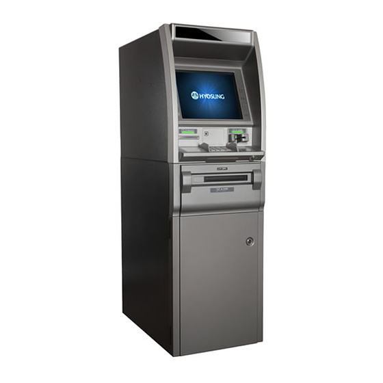
The customer selects transactions and requests information at the fascia. Customer Display Barcode Reader Card Reader Receipt Slot Printer Slot Encryption PIN Pad Upper Front Cash Dispenser Slot Shelf for bags (Option) © 2013 Nautilus Hyosung, Inc. All Rights Reserved. -
Page 19: Hardware Configuration
Service Manual Chapter2. System Configuration Hardware Configuration System Block Diagram ► System Block Diagram © 2013 Nautilus Hyosung Inc. All Rights Reserved. - Page 20 Troubleshooting Procedure ........................3-3 Associated electronic boards........................3-4 Inverter Board ............................3-12 Touch Screen ............................. 3-13 Encryption PIN Pad ............................3-14 Panel Control Board ............................3-16 Functionality ............................... 3-16 Barcode Scanner ............................... 3-17 © 2013 Nautilus Hyosung Inc. All Rights Reserved. Chapter3-I...
-
Page 21: Chapter3. User Handling Unit
Interface Connector of the TFT Module. 11. After installation of the TFT Module into an enclosure, do not twist nor bend the TFT Module even momentary. At designing the enclosure, it should be taken into © 2013 Nautilus Hyosung, Inc. All Rights Reserved. -
Page 22: General Specifications
Nominal Input Voltage VDD +3.3Volt (Typ.) Typical Power consumption 12.82 (64 Gray Bar Pattern, exclude inverter) Electrical Interface 1 Channel LVDS Surface Treatment Anti-glare type, Hardness 3H Support Colors 16.2M RoHS Compliance RoHS Compliance © 2013 Nautilus Hyosung Inc. All Rights Reserved. -
Page 23: Troubleshooting Procedure
2. Backlight of the LCD panel is on. -> Connect/Disconnect the power line of OPL assembly. -> If “Nautilus HYOSUNG” logo is not displayed on the OPL screen, replace the AD board. ► The LCD is displayed white -> Check the installation status of the LVDS cable inside the assembly. -
Page 24: Associated Electronic Boards
OSD MENU Selection / AUTO PC ANALOG Screen Automatic Adjustment HOT KEY LEFT (-) Left / MINUS / DOWN RIGHT (+) Right / PLUS / UP GREEN : ON : ST-BY OFF AMBER : SUSPEND(DPMS) © 2013 Nautilus Hyosung Inc. All Rights Reserved. - Page 25 OSD Horizontal Position HORIZONTAL Adjustment: 0~100 VERTICAL OSD Vertical Position Adjustment 0~100 WHITE Screen WHITE BALANCE D-SUB ONLY BALANCE Adjustment POWER Setting Y/N of LED INDICATION Operation FACTORY Screen Adjustment PRESET Setting Initialization © 2013 Nautilus Hyosung Inc. All Rights Reserved.
- Page 26 1 : NC 2 : VCC 1.8V LOCAL KEY 3 : GREEN CONTROL 4 : RED (CN301) 5 : GND (8 PIN WAFER) 6 : KEY1 7 : KEY2 8 : NC © 2013 Nautilus Hyosung Inc. All Rights Reserved.
- Page 27 B01, B03 : N.C B02 : 120 OHM, 10%, 5A, 2012, BEAD HU/CIS 5A IC1 : N.C L1 : N.C D1 : N.C EC1, EC2, : N.C EC3 : N.C 3.3V PANEL VCC OPTION © 2013 Nautilus Hyosung Inc. All Rights Reserved.
- Page 28 SCALER TTL DRIVE 4.RED 0V/3.3V SCALER TTL DRIVE 5.GND 6.KEY1 0~1.8V KEY Input 7.NC 8.NC CN302(4 PIN Voltage Current Remarks (TYP/MAX) (TYP/MAX) DOWNLOAD) 1.VCC 3.3V 2.RXD TTL 3.3V 3.TXD TTL 3.3V 4.GND © 2013 Nautilus Hyosung Inc. All Rights Reserved.
- Page 29 Remarks (TYP/MAX) (TYP/MAX) 1.GND 2.GND 3.A_YP3+ 4.A_YP3- 5.GND 6.A_CLK+ 7.A_CLK- 8.GND 9.A_YP2+ 10.A_YP2- 11.GND 12.A_YP1+ 13.A_YP1- 14.GND 15.A_YP0+ 16.A_YP0- 17.GND 18.GND BOE 15” HT150X02-100 / 19.PANEL VCC 3.3V(3.6V) 0.7(A) 3.3V 20.PANEL VCC © 2013 Nautilus Hyosung Inc. All Rights Reserved.
- Page 30 9.ST-5V 10.GND J14(DSUB 9 Voltage Current PIN Touch Remarks (TYP/MAX) (TYP/MAX) Screen to Host) 2.RXD 3.TXD 5.GND J10(4 PIN Door Voltage Current Remarks Sensor Input) (TYP/MAX) (TYP/MAX) 1.BKLT_EN 2.GND 3.NC 4.GND 3-10 © 2013 Nautilus Hyosung Inc. All Rights Reserved.
- Page 31 80 % (Typ.) Uniformity Contrast Ratio 500:1 (Typ.) Response Time Tr 3mS Tf 7mS (Typ. / 10%~90%) CIE Color Typ. Coordinates 0.313 White 6500K (±0.05 (based on 0.329 SET)) 0.646 0.343 © 2013 Nautilus Hyosung Inc. All Rights Reserved. 3-11...
-
Page 32: Inverter Board
DC Input Power (12V) No Connection BL ON/OFF CCFL Drive Signal BRT_ADJ 0~5V 3,4,7,8 2. CN2 Connector PIN No. Symbol Remark High Cold 3. CN3 Connector PIN No. Symbol Remark High Cold ► Appearance 3-12 © 2013 Nautilus Hyosung Inc. All Rights Reserved. -
Page 33: Touch Screen
▪ Do not give unnecessary strain to the FPC tail while assembling. ▪ Do not operate touch panel by applying excessive force. Operation ▪ Do not use a sharp thing for input. © 2013 Nautilus Hyosung Inc. All Rights Reserved. 3-13... -
Page 34: Encryption Pin Pad
Serial Communication during OFF USB/Serial OPEN Boot firmware download is Common for available for CLOSE. USB/Serial Power Connector Common for USB/Serial Serial Connector Common for USB/Serial CN10 USB Connector Common for USB/Serial 3-14 © 2013 Nautilus Hyosung Inc. All Rights Reserved. - Page 35 1. If LED1 is off, check the cable connection to see if the power supply is okay. 2. If LED1 is on and LED2 is off, it means EPP is in abnormal operation. Therefore, replace the EPP © 2013 Nautilus Hyosung Inc. All Rights Reserved. 3-15...
-
Page 36: Panel Control Board
Chapter3. User Handling Unit Service Manual Panel Control Board Functionality ▪ Control guidance Lights (Flickers) ▪ Control the POWER CONTROL signals ▪ Check SENSOR Signals ▪ Power Distribution 3-16 © 2013 Nautilus Hyosung Inc. All Rights Reserved. -
Page 37: Barcode Scanner
Service Manual Chapter3. User Handling Unit Barcode Scanner ► The image engine is a CMOS imager-based (black/white) module device for image capture and barcode decode. It supports reading 2D barcodes. © 2013 Nautilus Hyosung Inc. All Rights Reserved. 3-17... - Page 38 Troubleshooting Tools and Procedure ......................4-2 Field Repair Scope (Recommendation) ....................... 4-2 Troubleshooting Procedure .......................... 4-3 How to Clear Card Reader Jams ......................... 4-4 Preventive Maintenance ............................4-5 Cleaning ............................... 4-5 © 2013 Nautilus Hyosung Inc. All Rights Reserved. Chapter4-I...
-
Page 39: Overview
ATM card in the card entry slot to begin transactions. The card reader automatically pulls the card into the ATM and returns the card when the transaction is completed. © 2013 Nautilus Hyosung Inc. All Rights Reserved. -
Page 40: Chapter4. Card Reader
Connect a keyboard to the CE engine, and select a certain folder on the rear operator panel. Copy the files to a USB drive. Send the data to Nautilus Hyosung for more detailed analysis. However, in order to study the fault using the software file, the time of the fault occurrence is critical. -
Page 41: Troubleshooting Procedure
4. Determine if the error can be corrected in the field. 5. Take prompt measures if possible. Otherwise, replace the card reader. 6. When replacing a card reader, keep journal and log files. © 2013 Nautilus Hyosung Inc. All Rights Reserved. -
Page 42: How To Clear Card Reader Jams
2. If needed, open the shutter and retrieve the card by pressing and holding the plunger button (2) as shown. Then turn the wheel clockwise to force the card from the reader. © 2013 Nautilus Hyosung Inc. All Rights Reserved. -
Page 43: Preventive Maintenance
1. Using canned air, dust out any accumulated debris inside the card reader. This task must be performed from the front and rear of the ATM. 2. Clean magnetic head with a cleaning card. 3. Through diagnostics, test the functionality of the card reader. © 2013 Nautilus Hyosung Inc. All Rights Reserved. - Page 44 Chapter 5 Power Supply Contents Overview ................................5-1 Functional Description ..........................5-1 Troubleshooting ..............................5-2 Troubleshooting Tools ..........................5-2 Field Repair Scope (Recommendation) ....................... 5-2 Battery.................................. 5-3 Introduction ..............................5-3 © 2013 Nautilus Hyosung, Inc. All Rights Reserved. Chapter5-I...
-
Page 45: Chapter5. Power Supply
Failure Mode> and only [DC OUT] will be turned off. 6. [BATT OFF] S/W shall be pressed on “I”. If [BATT OFF] S/W is pressed on “O” position, the system will not enter <Power Failure Mode> and will be turned off. © 2013 Nautilus Hyosung Inc. All Rights Reserved. -
Page 46: Troubleshooting
► In the field, the technician can only replace the fuse. Other components shall be repaired and inspected at the depot level. The above scope is only a recommendation of Nautilus Hyosung and is subject to change depending on the field situation or the technician’s capacity. -
Page 47: Battery
In addition, this backup equipment is essential in the ATM to protect control electronics for the purpose of allowing the application program to shut down under normal operation. © 2013 Nautilus Hyosung Inc. All Rights Reserved. - Page 48 Installing Memory Module ........................... 6-15 Installing add-on Cards ..........................6-17 BIOS Setting ............................... 6-23 HDD ................................... 6-25 ODD ................................... 6-27 PCI USB Cable ..............................6-29 SYS FAN ................................6-31 CPU Cooler ................................ 6-33 © 2013 Nautilus Hyosung Inc. All Rights Reserved. Chapter6-I...
-
Page 49: Overview
USB Hub used to communicated with some devices like cash dispenser, card reader, receipt printer and EPP. The following picture will show you the major component and location used in Control Electronics. © 2013 Nautilus Hyosung Inc. All Rights Reserved. -
Page 50: Chapter6. Control Electronics
240-pin DDR3 SDRAM slots 5. ATX_POWER Standard 24-pin ATX power connector 6. SATA 6G 1, 2 Serial ATA 6.0Gb/s connectors 7. SATA1~4 Serial ATA 3.0Gb/s connectors 8. F_PANEL Front panel switch/LED header © 2013 Nautilus Hyosung Inc. All Rights Reserved. - Page 51 18. F_AUDIO Front panel audio header 19. PCIE1 PCI Express x1 slot 20. PCI1~2 32-bit add-on card slots 21. PCIEX16 PCI Express slot for graphics interface 22. ATX12V 4-pin +12V power connector © 2013 Nautilus Hyosung Inc. All Rights Reserved.
-
Page 52: Functional Description
F7 hot key for boot up devices option Form Factor Micro-ATX Size, 244mm x 220mm Internal I/O Connectors & Headers 1 x 24-pin ATX Power Supply connector 1 x 4-pin 12V Power connector © 2013 Nautilus Hyosung Inc. All Rights Reserved. - Page 53 2 x USB 2.0 headers support additional four USB 2.0 ports (F_USB1 support EZ charger) 1 x Case open header 1 x TPM header 1 x Serial port header(COM) 1 x Parallel port header(LPT) 1 x CLR_CMOS header © 2013 Nautilus Hyosung Inc. All Rights Reserved.
-
Page 54: Jumper Setting
OPEN. This illustration shows a 3-pin jumper. Pins 1 and 2 are SHORT. 2. Checking Jumper Setting The following illustration shows the location of the motherboard jumpers. Pin 1 is labeled. © 2013 Nautilus Hyosung Inc. All Rights Reserved. - Page 55 <Note!> To avoid the system instability after clearing CMOS, we recommend users to enter the main BIOS setting page to “Load Default Settings” and then “Save and Exit Setup”. © 2013 Nautilus Hyosung Inc. All Rights Reserved.
-
Page 56: Connecting Component
3. Connect the case switches and indicator LEDs to the F_PANEL. 4. Connect the system cooling fan connector to SYS_FAN. 5. Connect the auxiliary case power supply connector to ATX12V. 6. Connect the case speaker cable to SPK. © 2013 Nautilus Hyosung Inc. All Rights Reserved. - Page 57 CPU_FAN: CPU cooling FAN Connector Signal Name Function System Ground +12V Power +12V Sense Sensor <Note!> Users please note that the fan connector supports the CPU cooling fan of 1.1A ~ 2.2A (26.4W max) at +12V. © 2013 Nautilus Hyosung Inc. All Rights Reserved.
- Page 58 PS_ON Ground Ground Ground Ground Ground PWRGD +5VSB +12V +12V +3.3V Ground ► ATX12V: ATX 12V Power Connector Signal Name Ground Ground +12V +12V ► SPK: Speaker Header Signal Name Signal 6-10 © 2013 Nautilus Hyosung Inc. All Rights Reserved.
- Page 59 The time requirement is due to internal de-bounce circuitry. After receiving a power on/off signal, at least two seconds elapses before the power supply recognizes another on/off signal. © 2013 Nautilus Hyosung Inc. All Rights Reserved. 6-11...
-
Page 60: Installing The Processor (Cpu)
▪ Lift the tail of the load lever. ▪ Rotate the load plate to fully open position. C. Removing the Cap ▪ Be careful not to touch the contact at any time. 6-12 © 2013 Nautilus Hyosung Inc. All Rights Reserved. - Page 61 ▪ Engage the load lever while pressing down lightly onto the load plate. ▪ Secure the load lever with the hook under retention tab. F. Fasten the cooling fan supporting base onto the CPU socket on the motherboard. © 2013 Nautilus Hyosung Inc. All Rights Reserved. 6-13...
- Page 62 2. DO NOT remove the CPU cap from the socket before installing a CPU. 3. Return Material Authorization (RMA) requests will be accepted only if the motherboard comes with the cap on the LGA1155 socket. 6-14 © 2013 Nautilus Hyosung Inc. All Rights Reserved.
-
Page 63: Installing Memory Module
5. Install the DIMM module into the slot and press it firmly down until it seats correctly. The slot latches are levered upwards and latch on to the edges of the DIMM. 6. Install any remaining DIMM modules. © 2013 Nautilus Hyosung Inc. All Rights Reserved. 6-15... - Page 64 2. Attach the other cable end to the SATA hard drive. 3. Attach the SATA power cable to the SATA hard drive and connect the other end to the power supply. 6-16 © 2013 Nautilus Hyosung Inc. All Rights Reserved.
-
Page 65: Installing Add-On Cards
<Note!> Before installing an add-on card, check the documentation for the card carefully. If the card is not Plug and Play, you may have to manually configure the card before installation. © 2013 Nautilus Hyosung Inc. All Rights Reserved. 6-17... - Page 66 2. The onboard PCI interface does not support 64-bit SCSI cards. Connecting Optional Devices Refer to the following for information on connecting the motherboard’s optional devices: 6-18 © 2013 Nautilus Hyosung Inc. All Rights Reserved.
- Page 67 Front Panel USB Power USBPWR Front Panel USB Power USB_FP_P0- USB Port 0 Negative Signal USB_FP_P1- USB Port 1 Negative Signal USB_FP_P0+ USB Port 0 Positive Signal USB_FP_P1+ USB Port 1 Positive Signal © 2013 Nautilus Hyosung Inc. All Rights Reserved. 6-19...
- Page 68 BIOS. Pin 1-2 Function Short Chassis cover is removed Open Chassis cover is closed ME_UNLOCK: ME Unlock Header Pin 1-2 Function Short Unlock Open Lock 6-20 © 2013 Nautilus Hyosung Inc. All Rights Reserved.
- Page 69 This is a header that can be used to connect to the printer, scanner or other devices. Signal Name Signal Name STROBE ERROR INIT SLCT Ground Ground Ground Ground Ground Ground BUSK Ground Ground SLCT © 2013 Nautilus Hyosung Inc. All Rights Reserved. 6-21...
- Page 70 Use the three audio ports to connect audio devices. The first Audio Ports jack is for stereo line-in singal. The second jack is for stereo line-out singal. The third jack is for microphone. 6-22 © 2013 Nautilus Hyosung Inc. All Rights Reserved.
- Page 71 POST is a series of built-in diagnostics performed by the BIOS. After the POST routines are completed, the following message appears: 1. Press DEL to enter SETUP Press the delete key to access the BIOS Setup Utility. © 2013 Nautilus Hyosung Inc. All Rights Reserved. 6-23...
- Page 72 2. BIOS Main Menu When you enter the BIOS Setup program, the main menu appears, giving you an overview of the basic system information. Select an item and press <Enter> to display the submenu. 6-24 © 2013 Nautilus Hyosung Inc. All Rights Reserved.
-
Page 73: Hdd
► It is a storage device of CE module within ATM System (generic auxiliary storage device) to take installation CD to allow for OS (Windows 7) and AP program installation. HDD Sample Picture © 2013 Nautilus Hyosung Inc. All Rights Reserved. 6-25... - Page 74 Chapter6. Control Electronics Service Manual Screwable Point of HDD ODD (E: Drive) HDD2 (D: Drive) HDD1 (C: Drive) HDD SATA Cable connection 6-26 © 2013 Nautilus Hyosung Inc. All Rights Reserved.
-
Page 75: Odd
► It is a storage device of CE module within ATM System (generic auxiliary storage device) to take installation CD to allow for OS (Windows 7) and AP program installation. ODD( CDROM / DVD ROM ) Sample Picture © 2013 Nautilus Hyosung Inc. All Rights Reserved. 6-27... - Page 76 Chapter6. Control Electronics Service Manual ODD (E: Drive) HDD2 (D: Drive) HDD1 (C: Drive) ODD SATA Cable connection 6-28 © 2013 Nautilus Hyosung Inc. All Rights Reserved.
-
Page 77: Pci Usb Cable
Service Manual Chapter6. Control Electronics PCI USB Cable ► PCI USB Cable © 2013 Nautilus Hyosung Inc. All Rights Reserved. 6-29... - Page 78 Chapter6. Control Electronics Service Manual I/F Cable PCI USB Cable PCI Serial Card PCI Slot connection 6-30 © 2013 Nautilus Hyosung Inc. All Rights Reserved.
-
Page 79: Sys Fan
Service Manual Chapter6. Control Electronics SYS FAN ► SYS FAN SYSTEM FAN SYS FAN Location © 2013 Nautilus Hyosung Inc. All Rights Reserved. 6-31... - Page 80 Chapter6. Control Electronics Service Manual SYS FAN Cable connection FAN Power Connector 6-32 © 2013 Nautilus Hyosung Inc. All Rights Reserved.
-
Page 81: Cpu Cooler
Service Manual Chapter6. Control Electronics CPU Cooler ► CPU Cooler CPU Cooler © 2013 Nautilus Hyosung Inc. All Rights Reserved. 6-33... - Page 82 Chapter6. Control Electronics Service Manual CPU Cooler Cable connection 6-34 © 2013 Nautilus Hyosung Inc. All Rights Reserved.
- Page 83 Belt Tension Adjustment ..........................7-46 Gate Shutter Adjustment ..........................7-49 Exit Shutter Adjustment ..........................7-50 Preventive Maintenance ............................ 7-51 Cleaning..............................7-51 Lubrication ..............................7-52 Setting Specifications ............................7-54 Dip Switch Setting ............................7-54 © 2013 Nautilus Hyosung, Inc. All Rights Reserved. Chapter...
-
Page 84: Overview
Reject & Retract Box is an integral system that transfers defective bills from cash cassette to Reject Department while sending the bills withdrawn but not taken by customers to the Retract Department where the bills can be safely stored. © 2013 Nautilus Hyosung Inc. All Rights Reserved. -
Page 85: Appearance And Dimension
Service Manual Chapter7. Cash Dispenser Unit Appearance and Dimension ► The following figures show the three sectional diagrams of the cash dispenser. © 2013 Nautilus Hyosung Inc. All Rights Reserved. - Page 86 Because the Pick-up Module in the cash cassette is made of plastic, which is fragile and vulnerable to any shock, be careful not to drop or damage the cash cassette while handling or transferring the module. © 2013 Nautilus Hyosung Inc. All Rights Reserved.
-
Page 87: Basic Specifications
- Detection of cassette identification - Detection of available notes - Detection of multiple notes Detection Function - Note length and interval detection - Cassette position detection - Detection of bill empty in cassette © 2013 Nautilus Hyosung Inc. All Rights Reserved. -
Page 88: Types
1. Front access type 2. Rear access type © 2013 Nautilus Hyosung Inc. All Rights Reserved. -
Page 89: Functional Description
To convey normal bills to customers, the Exit Shutter should be opened or closed. The Shutter is designed to require the lock mechanism to prevent customers from opening the Shutter at their own discretion. © 2013 Nautilus Hyosung Inc. All Rights Reserved. - Page 90 Service Manual Chapter7. Cash Dispenser Unit ► Actuator Diagram Electro-magnetic components used for this cash dispenser are illustrated in figure below. © 2013 Nautilus Hyosung Inc. All Rights Reserved.
-
Page 91: Sensor
CS 11,21,31,41 Cassette Outlet Jam Detection Sensor CS 12,22,32,42 Cassette ID Sensor CS 16,26,36,46 Cash Low Sensor CS 17,27,37,47 Cassette Docking Sensor CS 18,28,38,48 Bill Empty Detection Sensor CS 19,29,39,49 Clutch Encoder Sensor © 2013 Nautilus Hyosung Inc. All Rights Reserved. - Page 92 Service Manual Chapter7. Cash Dispenser Unit ► Sensor Diagram Sensors used for this cash dispenser is illustrated in figure below. © 2013 Nautilus Hyosung Inc. All Rights Reserved.
-
Page 93: Block Diagram
Service Manual Chapter7. Cash Dispenser Unit Block Diagram ► Block Diagram of Controller Board 7-10 © 2013 Nautilus Hyosung Inc. All Rights Reserved. -
Page 94: Cable Connection Diagram
1,2,3,4 CASSETTE ID B/D GND MAIN POWER(+24V, GND) CN10 reserved CN11 reserved CN12 PLD DOWNLOAD CN13/CN14 EP DOWNLOAD CN15 reserved CN16 CN17 Shutter Solenoid / Sensor CN19 JTAG CN21/CN31 POWER(+5V,+12V,+24V,GND) CN30 DOCK 7-11 © 2013 Nautilus Hyosung Inc. All Rights Reserved. -
Page 95: Replacement
Exit Shutter Solenoid Presenter Presenter Assembly Cassette Latch, Assembly Push Plate Main Motor Depot Level Motor Assembly Delivery Motor only Cam Motor The other Depot Level components and Factory except above only described. 7-12 © 2013 Nautilus Hyosung Inc. All Rights Reserved. -
Page 96: Sensor Replacement
4 cassette identification sensors, 2 double bill detection sensors, 2 cam detection sensors, 1 withdrawal detection sensor and 2 gate operation detector sensor. ► Removal of Controller Protective Cover 7-13 © 2013 Nautilus Hyosung Inc. All Rights Reserved. -
Page 97: Transport Path Sensor
When assembling the Sensor Bracket Assembly, ensure to completely lift Sensor Bracket Assembly up to have identical position between the face of sensor and transport path, and then tighten the two bracket screws. 7-14 © 2013 Nautilus Hyosung Inc. All Rights Reserved. - Page 98 6. From the removed Sensor Bracket Assembly, remove the M3 sensor screws (1 place each) of the sensor which will be replaced. 7. Replace the sensor and then assemble the unit in the reverse order - 6~1. 7-15 © 2013 Nautilus Hyosung Inc. All Rights Reserved.
- Page 99 2. Loosen the M3 sensor fixing screw (1 place) of the sensor to replace from the removed Sensor Bracket. 3. Replace the sensor. 4. Assemble the unit in the reverse order of 2~1. 7-16 © 2013 Nautilus Hyosung Inc. All Rights Reserved.
- Page 100 7. Assemble the unit in the reverse order of 5~1. When assembling the Sensor Bracket Assembly, align the rectangular to the body groove and tighten the M4 fixing screw (1 place). 7-17 © 2013 Nautilus Hyosung Inc. All Rights Reserved.
- Page 101 6. Assemble the unit in the reverse order of 4~1. When assembling the Sensor Bracket Assembly, align the rectangular to the body groove and tighten the M4 fixing screw (1 place). 7-18 © 2013 Nautilus Hyosung Inc. All Rights Reserved.
- Page 102 6. Assemble the unit in the reverse order of 4~1. When assembling the Sensor Bracket Assembly, align the rectangular to the body groove and tighten the M4 fixing screw (1 place). 7-19 © 2013 Nautilus Hyosung Inc. All Rights Reserved.
- Page 103 Be careful not to break the connector pin when removing. 2. Loosen the M3 sensor fixing screw (1 place each) to replace from the fixed Sensor Bracket. 3. Replace the sensor. 4. Assemble the unit in the order of 2~1. 7-20 © 2013 Nautilus Hyosung Inc. All Rights Reserved.
- Page 104 2. Loosen the M3 sensor fixing screw (1 pace) of the sensor to replace from the removed Sensor Bracket. 3. Replace the sensor. 4. Assemble the unit in the reverse order of 2~1. 7-21 © 2013 Nautilus Hyosung Inc. All Rights Reserved.
- Page 105 2. Loosen the M3 sensor fixing screw (1 pace) of the sensor to replace from the removed Sensor Bracket 3. Replace the sensor. 4. Assemble the unit in the reverse order of 2~1. 7-22 © 2013 Nautilus Hyosung Inc. All Rights Reserved.
-
Page 106: Gate Operation Detection Sensor & Encoder Sensor
7. Before tightening screw of CS3 sensor completely, first release the flanger of the solenoid and make sure to adjust the detection bracket to the center of the sensor. After checking that, tighten screw completely. 7-23 © 2013 Nautilus Hyosung Inc. All Rights Reserved. - Page 107 3. Press the part ‘B’ of the sensor softly as shown in the below figure to remove the lock and the sensor. 4. To insert the sensor, insert the part ‘A’ first and press the part ‘B’ to lock. 5. Assemble this in the order of 3~1 7-24 © 2013 Nautilus Hyosung Inc. All Rights Reserved.
- Page 108 3. Press the part ② of the sensor softly as shown in the below figure to remove the lock and the sensor. 4. To insert the sensor, insert the part ① first and press the part ② to lock. 5. Assemble this in the order of 4~1. 7-25 © 2013 Nautilus Hyosung Inc. All Rights Reserved.
-
Page 109: Docking Sensor
4. Loosen the M3 sensor fixing screw (2 places) from the remove Sensor Bracket. 5. Replace the sensor. 6. Assemble in the order of 4~1. <Note!> Adjust cassette position when mounting it so that you can hear click sound from the switch. 7-26 © 2013 Nautilus Hyosung Inc. All Rights Reserved. - Page 110 4. Loosen the M3 sensor fixing screw (2 places) from the removed sensor supporter. 5. Replace the sensor and then assemble in the reverse order of 3~1. <Note!> Adjust cassette position when mounting it so that you can hear click sound from the switch. 7-27 © 2013 Nautilus Hyosung Inc. All Rights Reserved.
-
Page 111: Retract Box Full Sensor
2. Disconnect the connector and remove the cable tie to remove the Sensor Bracket. Be careful not to break the connector pin when removing. 3. Remove the sensor and replace this one. 4. Assemble in the order of 2~1. 7-28 © 2013 Nautilus Hyosung Inc. All Rights Reserved. - Page 112 2. Disconnect the connector and remove the cable tie to remove the Sensor Bracket. Be careful not to break the connector pin when removing. 3. Remove the sensor and replace this one. 4. Assemble in the order of 2~1. 7-29 © 2013 Nautilus Hyosung Inc. All Rights Reserved.
-
Page 113: Cash Low Sensor
6. To assemble the sensor in the bracket, lock it from the front side and press the rear side to fix it. <Note!> Adjust the sensor by running the variable resistance so that it generate below 1.0V if remaining amount is available. Otherwise, set it above 3.0V. 7-30 © 2013 Nautilus Hyosung Inc. All Rights Reserved. -
Page 114: Bill Withdrawal Detection Sensor (Cs15)
5. Replace the sensor. 6. Assemble this in the order of 4~1. To insert the sensor, insert the part ‘A’ first and press the part to lock. 7-31 © 2013 Nautilus Hyosung Inc. All Rights Reserved. -
Page 115: Cam Detection Sensor (Cs6, Cs7)
4. Press the part ‘B’ of the sensor softly as shown in the below figure to remove the lock and the sensor. 5. To insert the sensor, insert the part ‘A’ first and press the part ‘B’ to lock. 6. Assemble in the order of 4~1 7-32 © 2013 Nautilus Hyosung Inc. All Rights Reserved. -
Page 116: Bill Empty Detection Sensor (Cs18D, T Cs 28D, T Cs38D, T Cs48D, T)
Sensor Bracket. Be careful not to break the connector pin when removing. 3. Loosen M3 fixing screw (each 2 places) on the sensor to take out the sensor 4. Replace the sensor. 5. Assemble in the order of 3~1. 7-33 © 2013 Nautilus Hyosung Inc. All Rights Reserved. -
Page 117: Cassette Identification Sensor (Cs12, Cs22, Cs32, Cs42)
4. Remove the connector and the cable tie to remove the Sensor Bracket. Be careful not to break the connector pin when removing. 5. Replace the sensor. 6. Assemble in the order of 4~1. 7-34 © 2013 Nautilus Hyosung Inc. All Rights Reserved. -
Page 118: Sub-Assembly Replacement
3. Loosen the board M3 fixing screws (5 places in the main board and 4 places in the sub board). 4. Replace the board. 5. Assemble in the order of 4~1. 7-35 © 2013 Nautilus Hyosung Inc. All Rights Reserved. -
Page 119: Main Motor Assembly
4. Remove the knob and unscrew the M5 fixing screw (3 places) of the main motor. 5. Remove the main motor assembly and replace it. 6. Assemble by the order of 4~1. 7-36 © 2013 Nautilus Hyosung Inc. All Rights Reserved. -
Page 120: Delivery Motor Assembly
4. Loosen M3 fixing screw (6 places) on motor. 5. Remove the delivery motor assembly and replace it. 6. Assemble by the order of 4~1. 7-37 © 2013 Nautilus Hyosung Inc. All Rights Reserved. -
Page 121: Cam Motor Assembly
4. Loosen M3 fixing screw (3 places) on motor. 5. Remove the cam motor assembly and replace it. 6. Assemble by the order of 4~1. 7-38 © 2013 Nautilus Hyosung Inc. All Rights Reserved. -
Page 122: Gate Solenoid Assembly
3. Loosen the solenoid M3 fixing screw (3 places). 4. Remove the solenoid assembly and replace it. 5. Assemble in the order of 4~1. Adjust the gate according to the adjustment standard. 7-39 © 2013 Nautilus Hyosung Inc. All Rights Reserved. -
Page 123: Clutch Assembly
1. To remove the clutch, unscrew the encoder sensor bracket of the clutch to remove, as shown in the above figure, by unscrewing the M4 fixing screw (2 places). Then, unscrew the M4 fixing screw (3 places) at the opposite side. 7-40 © 2013 Nautilus Hyosung Inc. All Rights Reserved. - Page 124 100g(0.22 lb) to the direction ① and about 200g ~ 300g(0.44~0.66 lb) to the direction ② when the timing belt is pressed by about 3mm(0.12 inch), using the tension gauge. 7-41 © 2013 Nautilus Hyosung Inc. All Rights Reserved.
-
Page 125: Presenter Assembly
Be careful not to break the connector pin when removing 2. Loosen M4 fixing screw (2 places) and M3 fixing screw (2 places) on conjunction of Presenter assembly and upper feeding assembly 7-42 © 2013 Nautilus Hyosung Inc. All Rights Reserved. -
Page 126: Cassette Assembly
2. Loosen latch bracket M3 screw (2 places) as shown in the figure and remove it from the cassette body. 3. Press the latch snap lock with hands to remove the latch from the latch bracket. 4. Replace the latch. 5. Assemble in the order of 3~1. 7-43 © 2013 Nautilus Hyosung Inc. All Rights Reserved. - Page 127 Remove the spring connected to the push plat hole at the same time. 3. Replace the push plate. 4. Assemble in the order of 2~1. Adjust the push plate groove to the push plate guide in time of assembly. 7-44 © 2013 Nautilus Hyosung Inc. All Rights Reserved.
-
Page 128: Adjustment
Gate Shutter Solenoid technician and depot Exit Shutter Exit Shutter Solenoid Level Cassette Width Guide and Height Guide Guide Factory Cassette Overlap length between Feed Roller and Gate Roller Adjustment Overlap Only 7-45 © 2013 Nautilus Hyosung Inc. All Rights Reserved. -
Page 129: Belt Tension Adjustment
400~600g, and tighten the screw completely. Make sure that the screw is not loose which can loosen the belt tension. 4. Slowly turn the Green Knob and double check if any belt vibration exists. 7-46 © 2013 Nautilus Hyosung Inc. All Rights Reserved. - Page 130 400~600g and then tighten the screw completely. Make sure the screw is not loose which can loosen the belt tension. 4. Slowly turn the Green Knob and double check if any belt vibration exists. 7-47 © 2013 Nautilus Hyosung Inc. All Rights Reserved.
- Page 131 400~600g and tighten the screw completely. Make sure the screw is not loose which can loosen the belt tension. 4. Slowly turn the Green Knob and double check if any belt vibration exists. 7-48 © 2013 Nautilus Hyosung Inc. All Rights Reserved.
-
Page 132: Gate Shutter Adjustment
3. Adjust the solenoid bracket so that the gate upper is at least 3.6mm away from the guide as shown in the below left figure 4. Tighten the solenoid M4 screws (2 places). 7-49 © 2013 Nautilus Hyosung Inc. All Rights Reserved. -
Page 133: Exit Shutter Adjustment
The ‘Y’ assembly value is supposed to become normal again by the spring. However, it is important to check the “alignment” because problems can occur if the Flanger of the Solenoid has not been connected horizontally. 7-50 © 2013 Nautilus Hyosung Inc. All Rights Reserved. -
Page 134: Cleaning
Feed Roller using the soft brush, Q-tip Pick up Gate Roller with alcohol Module in Cassette Y2 or Replace only rubber of Rubber of Pick-up Roller 1,000,000 Pick-up Roller with new count 7-51 © 2013 Nautilus Hyosung Inc. All Rights Reserved. -
Page 135: Lubrication
Gear support gear Initial AlbaniaGreaseEP1 teeth surface Oiling Initial Gate spring hook AlbaniaGreaseEP1 Oiling Gear support spring Initial AlbaniaGreaseEP1 hook Oiling Pick-up Module gear Initial AlbaniaGreaseEP1 teeth surface Oiling 7-52 © 2013 Nautilus Hyosung Inc. All Rights Reserved. - Page 136 Service Manual Chapter7. Cash Dispenser Unit Gate Spring Hook Gate Support Spring Hook Tension Pulley 7-53 © 2013 Nautilus Hyosung Inc. All Rights Reserved.
-
Page 137: Setting Specifications
- Press the ‘Initialize’ button on Cash Dispenser diagnostic mode - If error is not clear in case above actions are taken : Run the Automatic Sensor Adjustment mode (Dip switch 3 Off/On) 7-54 © 2013 Nautilus Hyosung Inc. All Rights Reserved. - Page 138 How to disassemble END Detection Sensor (MS1) ................... 8-12 How to disassemble spring......................... 8-13 How to disassemble Guide ......................... 8-14 How to disassemble Motor ......................... 8-15 How to disassemble PCBA......................... 8-16 © 2013 Nautilus Hyosung, Inc. All Rights Reserved. Chapter8-I...
- Page 139 (Refer to the assembly diagram and adjustment standard.) 11. Do not operation or function test under the strong light to avoid the malfunction of sensor or abnormal operation of machine. © 2013 Nautilus Hyosung Inc. All Rights Reserved.
-
Page 140: Preventive Maintenance
Regular Inspection Item & Cycle ► Regular Inspection Item & Cycle Regular Inspection Inspection Cleaning Checking Adjustment Lubrication Cycle Item Sensor Inspection, Cleaning Transport Path Cleaning Outlet Motor Gear Inspection & Lubrication TPH & Platen Cleaning © 2013 Nautilus Hyosung, Inc. All Rights Reserved. -
Page 141: Cleaning
▪ If the receipt printer needs to be disassembled, be sure to put it on the flat surface without the salience after disassembling. Also, there aren’t swing or interference of other object. ▪ Do not lean or overturn the receipt printer. © 2013 Nautilus Hyosung Inc. All Rights Reserved. -
Page 142: Lubrication
0.1g of Grease corresponds to the amount that is squeezed 1.2mm [1.05 inch] with the grease gun having the 7 mm [0.27 inch] feeder entry. ► Type of lubricants 1. Grease(G1): Shell Albania Grease EP1 2. Tellus: Shell Tellus #100 © 2013 Nautilus Hyosung, Inc. All Rights Reserved. -
Page 143: Oiling Criteria
▪ Use a piece of soft and dry cloth when removing dust, oil or grease, or cleaning the part or the assembly parts. ▪ Be careful that the paper contact side in the paper return path is not wet with oil. © 2013 Nautilus Hyosung Inc. All Rights Reserved. -
Page 144: Oiling Criteria For Each Module
Chapter8. Receipt Printer Service Manual Oiling Criteria for each module ► Spring Hook © 2013 Nautilus Hyosung, Inc. All Rights Reserved. - Page 145 Service Manual Chapter8. Receipt Printer ►Gear © 2013 Nautilus Hyosung Inc. All Rights Reserved.
-
Page 146: Part Replacement
MOTOR:20P020S0-08002 PCBA:K-SPR1VE_SERIAL How to disassemble receipt printer to three sections ► To replace the part, disassemble the receipt printer to three sections as the picture below, ① ASSY:OUTLET ② ASSY:TPH_SUPPORT ③ ASSY:MAIN_FRAME © 2013 Nautilus Hyosung, Inc. All Rights Reserved. - Page 147 ► How to disassemble, ④ SCR:PH_M3X10 x3ea ⑤ SCR:M3X6 (S) 1. Remove the screw (④) and disassemble ASSY:TPH_SUPPORT (②) from ASSY:MAIN_FRAME (③) 2. Remove the screw (⑤). Then disassemble ASSY:OUTLET (①) and ASSY:TPH_SUPPORT (②) © 2013 Nautilus Hyosung Inc. All Rights Reserved.
-
Page 148: How To Disassemble Tph
Chapter8. Receipt Printer Service Manual How to disassemble TPH ► Disassembling TPH ① SCR:PH_M3x8 x4ea ② TPH:AM_ATP82_SPR ③ ASSY:TPH_OUTLET 1. Remove the screws (①, SCR: PH_M3x8 x4ea) and disassemble TPH. 8-10 © 2013 Nautilus Hyosung, Inc. All Rights Reserved. -
Page 149: How To Disassemble Jam Sensor (Ms3)
Service Manual Chapter8. Receipt Printer How to disassemble Jam Sensor (MS3) ► Disassembling TPH ① SENSOR:P-INTERRUPTER ② BRACKET:JAM_SENSOR ③ SCR:PH_M3X6 1. Remove the screw (③) and disassemble BRACKET:JAM_SENSOR (②) © 2013 Nautilus Hyosung Inc. All Rights Reserved. 8-11... -
Page 150: How To Disassemble End Detection Sensor (Ms1)
How to disassemble END Detection Sensor (MS1) ► Disassembling END Detection Sensor (MS1) ① GUIDE_LOWER ② END_SENSOR:SPR26 1. Disassemble the sensor using “-“ driver (Hole of A). 2. Disconnect the connector from PCBA of Main_Frame. 8-12 © 2013 Nautilus Hyosung, Inc. All Rights Reserved. -
Page 151: How To Disassemble Spring
Chapter8. Receipt Printer How to disassemble spring ► Disassembling Spring ① SPRING:ROLLER_LEFT ② SPRING:ROLLER_RIGHT ③ SPRING:SUPPORT_UPPER_GUIDE_RIGHT ④ SPRING:SUPPORT_UPPER_GUIDE_LEFT 1. Disassemble the springs (4ea) from ASSY:OUTLET. 2. After replacing spring, be sure to lubricate. © 2013 Nautilus Hyosung Inc. All Rights Reserved. 8-13... -
Page 152: How To Disassemble Guide
Chapter8. Receipt Printer Service Manual How to disassemble Guide ► Disassembling Guide View “A” Spring ① GUIDE:SPR_UPPER 1. Lift up the spring and disassemble the guide. (Refer to View “A”) 8-14 © 2013 Nautilus Hyosung, Inc. All Rights Reserved. -
Page 153: How To Disassemble Motor
Service Manual Chapter8. Receipt Printer How to disassemble Motor ► Disassembling Motor ① SCR:PH_M2X6 x2ea ② STEP_MOTOR:20P020S0-08002 1. Remove the screws (2ea, ①) and disassemble the motor (②). © 2013 Nautilus Hyosung Inc. All Rights Reserved. 8-15... -
Page 154: How To Disassemble Pcba
How to disassemble PCBA ► Disassembling PCBA ①② ASSY:OUTLET, TPH ③ ASSY:MAIN_FRAME ④ SCR:M3X6 TAP x 4ea ⑤ COVER:PCBA 1. Unfasten the screw (④) and disassemble PCBA (⑤) from ASSY:MAIN_FRAME (③) 8-16 © 2013 Nautilus Hyosung, Inc. All Rights Reserved.
Need help?
Do you have a question about the MONiMAX5600 and is the answer not in the manual?
Questions and answers