Table of Contents
Advertisement
Quick Links
Advertisement
Table of Contents

Related Manuals for Cleco 7PTHDA Series


Summary of Contents for Cleco 7PTHDA Series
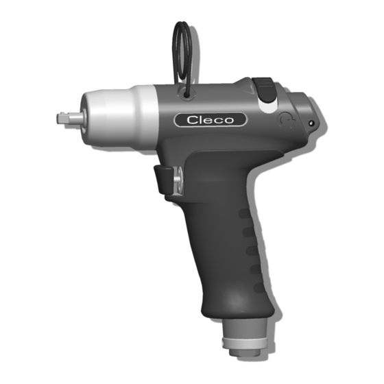
- Page 1 Instruction Manual P1880E/EN 2008-08 7PTHD… Pulse shut-off nutsetter...
- Page 2 Notes on this instruction manual The instruction manual has the following purposes: • It provides important instructions for safe and effective operation. • It describes the function and operation of the pulse shut-off nutsetter. • It serves as a reference work for technical data, service intervals and spare part orders.
-
Page 3: Table Of Contents
Contents Safety Warnings and notes ................5 Basic requirements for safe working practices ........6 Operator training................... 6 Personal protective equipment ............. 7 Designated use..................7 Noise and vibration ................7 Items supplied Product description Operation and functional elements ............8 Before initial operation Ambient conditions ................ - Page 4 Pulse unit .................... 32 Equipment order list................34 Technical data Dimensions 7PTHD… in mm.............. 35 Dimensions 7PTHDA… in mm ............36 Performance Data................36 Service Disposal P1880E/EN 2008-08 P1880E_EN 7PTHD 2008-08IVZ.fm, 18.08.2008...
-
Page 5: Safety
Safety Safety Warnings and notes Warning notes are identified by a signal word and a pictogram: • The signal word describes the severity and the probability of the impending danger. • The pictogram describes the type of danger. WARNING! Indicates a potentially hazardous situation which, if not avoided, could result in death or serious injury. -
Page 6: Basic Requirements For Safe Working Practices
Safety Basic requirements for safe working practices You should read all instructions. Failure to observe the instructions listed below can result in serious injuries. CAUTION! Work with a maximum working pressure of 101.5 psi (700 kPa) (measured as the air inlet ➔... -
Page 7: Personal Protective Equipment
Items supplied Personal protective equipment • Wear the protective goggles to protect against sprays of metal splinters and fluids. • Wear gloves to protect against skin irritation in case of direct contact with oil. Danger of injury by being wrapped up in and caught by machinery •... -
Page 8: Product Description
Items supplied Product description Operation and functional elements 1/4" 7PTHDA… Alternative position 1/4" 7PTHD… Abb. 3-1 Item Designation Reverse switch Torque adjustment, see 4.5.1 Setting the torque, page 10 Speed adjustment, see 4.5.2 Changing the speed, page 11 Air inlet Connection for Pneumatic Torque Verifier TVP100, signal connection kit, order no. -
Page 9: Before Initial Operation
Before initial operation Before initial operation Ambient conditions Ambient temperature 41 °F (5 °C) to a maximum of +104 °F (+40 °C) Permissible relative humidity 25 to 90 %, non-condensing Air supply Parameter Data Air hose Inner diameter 3/8" (ø 9.5 mm), maximum length 16' 4.85"... -
Page 10: Connect The Tool
Before initial operation Connect the tool. CAUTION! The air hose can come off by itself and whip around uncontrollably. Shut off the compressed air before making the connection. ➔ Connect the connection couplings to the tool and compressed air line properly. ➔... - Page 11 Before initial operation 1. Hold the output drive firmly. 2. Carefully push the size 2 hex wrench through the hole of the pistol grip housing until it reaches the torque adjustment screw Drehmoment 3. Turn the torque adjustment screw and roughly set the required torque, see Abb.
-
Page 12: Troubleshooting
Troubleshooting 4.5.3 Measuring the torque We recommend carrying out a static torque measurement by retightening the rundown. When carrying out a dynamic measurement using a transducer adapter, also carry out a static test, for example using a torque wrench (electronic). Troubleshooting Error Possible causes... -
Page 13: Maintenance
Maintenance Maintenance CAUTION! Danger of injury due to unintentional activation – before service, disconnect the tool from the compressed air supply. Service schedule Regular maintenance reduces operating faults, repair costs and downtime. Mainte- Measures Rundowns nance interval 100,000 Check the suspension bail for functional safety. ➔... - Page 14 Maintenance 6.1.1 Calculating a customer-specific maintenance plan A service interval W(1,2,3) depends on the following factors: Factor Value assumed in Description 6.1, "Maintenance plan" W1 = 100,000 Number of rundowns after a maintenance measure is pre- W2 = 500,000 scribed by Apex Tool Group. W3 = 1,000,000 1.8 seconds Specific rundown time, measured in life and endurance tests.
-
Page 15: Activating The Reserve Oil
Maintenance Activating the reserve oil If pulse build-up stops, some of the oil in the pulse unit has been used up. The reserve oil must be activated. If the equalizing piston reaches the limit stop, oil must be refilled the next time (see 6.3 Refilling oil, page 16). -
Page 16: Refilling Oil
Maintenance Refilling oil Approx. 7 oz. (200 ml) Approx. 0.20 oz (6 ml) – Item Designation Oil filling device asm. Oil filling device without filling piece Filling piece asm. Oil order no. 925715, ESSO-UNIVIS HVI26, approx. 2.1 qt (2 liters), temperature 68 ±9 °F (20 ±5 °C) Quick disconnect coupling Working pressure 65 –... - Page 17 Maintenance Remove the threaded pin 15 and ball 14. Remove the O-ring 12 and sleeve 13. Align the output drive and claw as shown in the illustration, see 6.2 Activating the reserve oil, page Rotate the equalizing piston 11 clockwise as far as it will go until X = 0 (starting point). Unscrew the equalizing piston 11 counterclockwise by 2.5 turns (reserve oil).
- Page 18 Maintenance P1880E/EN 2008-08 81c_Wartung en bedingt.fm, 18.08.2008...
-
Page 19: Repair Instructions
Repair instructions Repair instructions Refer also to 8 Spare parts, page 25 and 8.5 Equipment order list, page 34 Disassembling the motor unit <C3> <C3> <61> <C2> <54> <C1> <59> <C1> <59> Changing blades Changing bearings / rotors Disassembling the throttle valve <G>... -
Page 20: Disassembling The Impulse Unit
Repair instructions Disassembling the impulse unit Size 1/2" CAUTION! Skin irritation in case of direct contact with oil. Wear protective gloves. <D3> CAUTION! Hydraulic blade is under spring pressure! Wear protective goggles. <65> <D2> NOTE <D1> Permitted only if filling is guaranteed with oil filling device, see . - Page 21 Repair instructions 7.4.1 Assembling the end plate <59> <C8> <54> <59> <54> <55> <C4> <C5> <C6> <C7> Dimension X = 0.00" to 0.00236" (0.00 to 0.06 mm) 1. Press in <59>, see dimension X. Test force 1.12 – 3.37 lbf (5 – 15 N) Dimension Y = 0.0002"...
- Page 22 Repair instructions 7.4.2 Assembling the shut-off piston Size 4 <44> Don’t use grease – <45> to hold the balls in place! <47> <48> <49> (3×) <59> <44> <47> <50> P1880E/EN 2008-08 81d_Reparatur en bedingt.fm, 18.08.2008...
- Page 23 Repair instructions 7.4.3 Assembling the actuating ring <E> <E> <32> <32> click! <34> <44> <40> 33 (3×) <47> <55> <56> <60> Dimension X (Inch) <34> < 0.022" (0,55 mm) 935465 0.028±0.006" (0,7±0,15 mm) 935464 > 0.033" (0,85 mm) 935463 <34> Dimension X = <44>...
-
Page 24: Assembling The Pulse Unit
Repair instructions Assembling the pulse unit NOTE To prevent damage, lubricate the gaskets and O-rings using grease (order no. 914392) before assembly. 7.5.1 Assembling the hydraulic blades <78> <73> <77> <73> <F1> <F1> <77> <75> <76> (2×) <74>(2×) Size 1/2" <F2>... -
Page 25: Spare Parts
Spare parts Spare parts Note Always use only original CLECO replacement parts. Failure to comply with this instruction can result in decreased performance and an increased need for maintenance. Installing replacement parts from other manufacturers will void all manufacturer's warranties. -
Page 26: Pistol Grip 7Pthd
Spare parts Pistol grip 7PTHD… 0,7±0,1 Nm 0.5±0.1 lbf.ft 1 / ISO 4757 click (22) (24) 0,7 ±0,1 Nm 0.5 ±0.1 lbf.ft 935490 SW2 1,5+0,2 Nm 1.1+0.15 lbf.ft 3+1 Nm 931030 SW2,5 2.2+1 lbf.ft <G>: 933375 20+2 Nm 14.8+1.5 lbf.ft SW17 Connection for evaluation electronics TVP100 Adhesive, order no. - Page 27 Spare parts Index Description 935662 pistol grip housing asm. 934917 pipe plug M 5X5 935438 K1 muffler 935434 exhaust air throttle 922660 K1 o-ring 16,X1,5 935437 air inlet 905031 K1 screen 905599 K1 circlip 11,X1, IR S905998 1 K1 set bolt M 4X4 935673 reverse button...
-
Page 28: Pistol Grip 7Pthda
Spare parts Pistol grip 7PTHDA… P1880E/EN 2008-08 80e_Ersatzteile en.fm, 20.08.2008... - Page 29 Spare parts Index Description 935696 pistol grip housing asm. 934917 pipe plug M 5X5 935438 K1 muffler 935434 exhaust air throttle 922660 K1 o-ring 16,X1,5 935437 air inlet 905031 K1 screen 905599 K1 circlip 11,X1, IR S905998 1 K1 set bolt M 4X4 935673 reverse button...
-
Page 30: Motor Unit 935955
Spare parts Motor unit 935955 Axial clearance, see 7.4.1 Assembling the end plate, page 21 Reference dimension X, see 7.4.3 Assembling the actuating ring, page 23 P1880E/EN 2008-08 80e_Ersatzteile en.fm, 18.08.2008... - Page 31 Spare parts Index Description 935479 K1 washer 7,1 X 2,4 X 1,5 902862 K1 circlip 10,X1, AR 935443 actuating ring 935405 K1 ball 4,76MM (3/16") 935463 K1 ball sleeve 3,8 Ø6 X 3,8MM 935464 K1 ball sleeve 3,5 Ø6 X 3,5MM 935465 K1 ball sleeve 3,2 Ø6 X 3,2MM...
-
Page 32: Pulse Unit
Spare parts Pulse unit Tightening torque, see 7.5 Assembling the pulse unit, page 24 For disassembly, note the position of the balls in the control disc. Reassmble the balls in the same position P1880E/EN 2008-08 80e_Ersatzteile en.fm, 18.08.2008... - Page 33 Spare parts Index Description pulse unit 922666 K2 o-ring 13 × 1,5 902853 K2 o-ring 19, X1,5 935682 equalizing piston 916088 K2 o-ring 24,X1,5 935652 K2 sleeve 935950 hydraulic cylinder 926562 needle roller 2, X7,8 hydraulic rotor asm. 932222 K2 compression spring 935676 control blade asm.
-
Page 34: Equipment Order List
Spare parts Equipment order list Index Description 928476 Oil filling device 928483 Oil filling unit 931968 Joining piece cpl. 925730 Syringe 938539 Assembly/Disassembly motor unit 933484 Support 933481 Semi-monocoque pair 933480 Punch 933472 Support 0 mm 933473 Support 0,02 mm 933474 Support 0,04 mm 933475... -
Page 35: Technical Data
Technical data Technical data Dimensions 7PTHD… in mm Abb. 9-1 P1880E/EN 2008-08 80f_TechnDaten en.fm, 18.08.2008... -
Page 36: Dimensions 7Pthda
Technical data Dimensions 7PTHDA… in mm Abb. 9-2 Performance Data Order no. Recommended Free Air consumption torque range speed ft.lbf (Nm) /min (m /min) min. max. lb (kg) Free speed Pulses 7PTHD602 1.81 (0,82) 1/4" 8.83 (0,25) 7.06 (0,20) 7PTHDA602 1.92 (0,87) 2.9 (4) 5.2 (7) -
Page 37: Service
Service Service NOTE If repair is required send the complete 7PTHD… to Apex Tool Group. It may be repaired only by authorized technicians. If the tool is opened, the warranty is voided. Disposal CAUTION! Injuries and environmental damage from improper disposal. The components and auxiliary materials of a machine incorporate risks to health and the envi- ronment.
Need help?
Do you have a question about the 7PTHDA Series and is the answer not in the manual?
Questions and answers