Advertisement
Quick Links
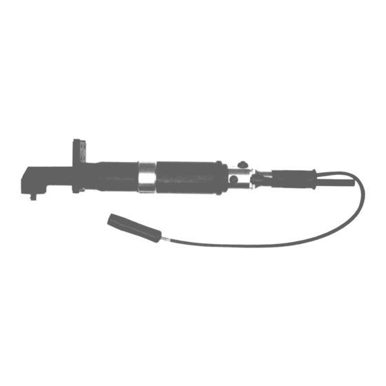
75NLTVCE Series Solenoid
Controlled Encoder Nutrunners
Series:
75
Nutrunner:
Handle:
L
Lever
Transducer:
Options:
V
Vision (Lights)
VP
Vision (Lights) Positive
Solenoid Controlled:
Encoder:
NORTH AMERICA
P.O. Box 1410
Lexington, SC 29071
N
L
T XX C E -
75
Operation & Service Manual
823093
X
X
-
X
Angle Terminations:
V
VHD Hold & Drive
X
Gear Train Designation:
2
4
3
6
EUROPE
Postfach 30
D-73461 Westhausen
2/01
Output Drive:
4
1/2"
5
5/8"
6
3/4"
S
Built-in Socket
(Specify Size)
T
Threaded Spindle
1
Advertisement

Related Manuals for Cleco 75NLTVCE Series


Summary of Contents for Cleco 75NLTVCE Series
- Page 1 Operation & Service Manual 823093 2/01 75NLTVCE Series Solenoid Controlled Encoder Nutrunners T XX C E - Series: Output Drive: 1/2" 5/8" Nutrunner: 3/4" Handle: Built-in Socket Lever (Specify Size) Angle Terminations: Transducer: Threaded Spindle VHD Hold & Drive Options:...
- Page 2 Avoid continuous vibration exposure. Keep wrists straight. Avoid repeated bending of wrists and hands. Cleco nutrunners are designed to operate on 90 psig (6.2 bar) maximum air pressure. If the tool is properly sized and applied, higher air pressure is unnecessary. Exces-...
- Page 3 Safety Recommendations exposure to cold and dampness, diet, smoking and work Work gloves with vibration reducing liners and wrist sup- practices are thought to contribute to the conditions. ports are available from some manufacturers of industrial work gloves. Tool wraps and grips are also available from Any tool operator should be aware of the following warning a number of different manufacturers.
- Page 4 OPERATING INSTRUCTIONS FOR YOUR SAFETY AND THE SAFETY OF OTHERS, READ AND UNDERSTAND THE SAFETY RECOMMENDATIONS ON PAGES 2 & 3 BEFORE OPERATING A NUTRUNNER. LUBRICATION TORQUE ADJUSTMENT An automatic in-line filter-lubricator-regulator is recom- The 75NLTVCE nutrunner is designed to develop maxi- mended as it increases tool life and keeps the tool in mum rated torque at 90 psig.
- Page 5 SERVICE INSTRUCTIONS DISASSEMBLY — GENERAL IMPORTANT: Transducer and motor can be removed from the front of the motor housing without disassem- bling handle and motor housing. Disconnect tool from air supply. Clamp the right angle head in a vise and loosen (left hand threads) the motor housing. Hold the tool in a vertical position with the right angle head up.
- Page 6 SERVICE INSTRUCTIONS REASSEMBLY — GENERAL When installing needle bearings, press only on the bear- The tool is reassembled in the reverse order of disassembly. ing's stamped end. The pinion needle bearing should be Clean all parts thoroughly in solvent and inspect for damage slipped on the pinion gear and pressed into the housing to or wear.
-
Page 7: Transducer Specifications
TRANSDUCER SPECIFICATIONS MAXIMUM TORQUE CAPACITY 147 ft. lbs. (200 Nm) OUTPUT VOLTAGE (Vo) 2 Millivolts per volt at maximum torque capacity BRIDGE RESISTANCE (Rbr) 700 ohms (nominal) can be used with 350 and 700 ohm strain gage equipment* TRANSDUCER CABLE No. - Page 8 55 & 75 NLTVCE RIGHT ANGLE TOOL WIRING DIAGRAM 19 PIN CONNECTOR + EXCITATION WHITE WHITE BLACK - EXCITATION TRANDUCER BLACK GREEN + SIGNAL GREEN CAMBION CONNECTORS - SIGNAL SHIELD SHIELD WHITE ENCODER "B" SIGNAL WHITE GREEN ENCODER GREEN ENCODER "B" COMMON BLACK BLACK ENCODER "A"...
-
Page 9: Encoder Specifications
ENCODER SPECIFICATIONS SUPPLY VOLTAGE: +5 TO +15V DC INPUT CURRENT: 4mA @ +15V DC OPERATING FREQUENCY: 10kHz PULSES PER REVOLUTION: 36(WITH QUADRATURE) SIGNAL B TO ELECTRONICALLY TRAIL SIGNAL "A" BY 90° ENCODER PULSES PER SPINDLE REVOLUTION BASED ON A 36 TOOTH ENCODER WHEEL. EXAMPLE: NUMBER OF PULSES = TOTAL GEAR REDUCTION x NUMBER OF TEETH ON ENCODER WHEEL. - Page 10 SOLENOID SPECIFICATIONS (+) SOLENOID 6V DC-8V DC CONTINUOUS VOLTAGE 24V DC-36V DC FOR 15 msec MAX. 14.95ohm RESISTANCE BLACK (-) SOLENOID TOOL RECEPTACLE CABLE CONNECTORS ADJUSTMENT SCREW SOLENOID RETAINER PLUNGER PIN .015/.020 1. Solenoid plunger pin to hat dimension should be .015/.020 as shown. A new plunger pin should be spaced as shown;...
- Page 11 5/64 HEX WRENCH ADJUSTMENT SCREW SOLENOID RETAINER PLUNGER PIN SOLENOID SEAT VALVE PLUNGER 4. Using a 5/64" hex wrench, turn adjustment screw clockwise until plunger pin is pressed through hat and valve plunger is fully seated in solenoid seat. 5. Depress throttle and check tool for rated speed at 90PSI. If tool does not perform according to specifications, valve plunger may not be fully depressed.
- Page 12 847659 869877 869878 869879 "V" & "X" RIGHT ANGLE HEADS 869882 "V" 883720 "X" 869874 "V" 861903 "V" 867546 869875 "X" 869880 861905 "X" 864711 864710 864712 867997 861903 "V" 869886 "V" 1/2" 869881 "V" 869876 "V" 861905 "X" 869883 "V" 5/8" 812222 "X"...
- Page 13 75NLTVCE NUTRUNNER GEAR TRAINS Part No. Model Part No. Model Part No. Model 869907-6 869908-4 869900-1 869907-6 869908-4 869900-1 869907-6 869908-4 869899-5 869907-6 869908-4 869899-5 Part No. Model 869902-7 Part No. Model 869903-5 NONE 869902-7 NONE 832125-9 869903-5 869901-9 869901-9 812164-2 844774-0 Part No.
-
Page 14: Parts List - Motor
75NLTVCE NUTRUNNER MOTOR 203799-2 203796-8 869923-3 812918-1 865352-9 847528-7 869925-8 203149-0 847528-7 869927-2 PARTS LIST — MOTOR PART NO. NAME OF PART QTY. PART NO. NAME OF PART QTY. 203149 Cylinder 865352 Rotor Lock Nut (incl. 812918) 203796 Motor Spacer 869923 Front Bearing Plate 203799... - Page 15 75NLTVCE HANDLE & MOTOR HOUSING...
- Page 16 PARTS LIST 75NLTVCE HANDLE & MOTOR HOUSING PART NO. NAME OF PART QUANITY 202012 Muffler 202174 Throttle Valve* 202182 Handle 202183 Cable Connector 202724 Pipe Cable Protector 203008 "O"-Ring 2/2" x 2/4" 203053 Retaining Ring 203259 PC Board (Negative Common) 203263 Light Ring (Rear) 203350...
- Page 17 "V" RIGHT ANGLE HOLD & DRIVE HEAD 847659-0 869877-1 869878-9 869879-7 867924-3 204384-2 867546-4 869880-5 204385-9 864711-7 864712-5 864710-9 867997-9 204350-3 204349-5 204346-1 622772-2 204344-5 842160-4 617290-2 204355-2 204345-3 PART NO. DESCRIPTION QTY. 204344 DRIVE SPINDLE 204345 BEARING CAP 204346 HOLD SPINDLE 204347 CLAMP RING†...
- Page 19 NOTES...
- Page 20 670 Industrial Drive Lexington, SC 29072 Phone: (803) 359-1200 Fax: (803) 359-2013...
Need help?
Do you have a question about the 75NLTVCE Series and is the answer not in the manual?
Questions and answers