Table of Contents
Advertisement
Quick Links
*931218-00*
931218-00
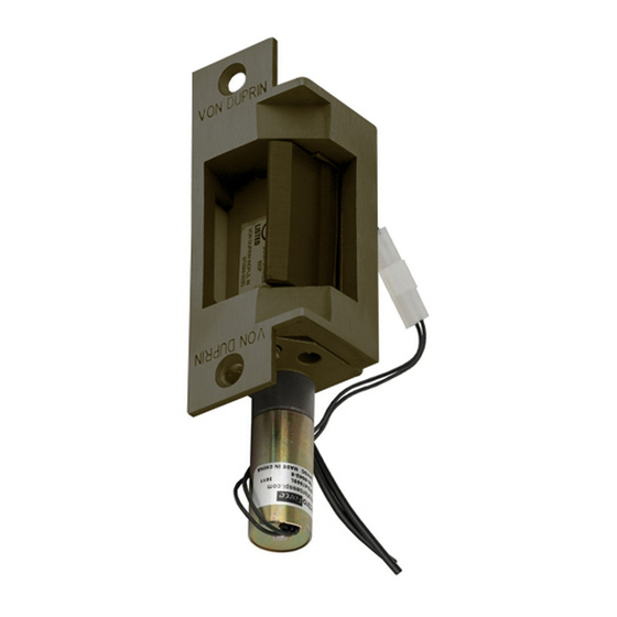
Electric Strike, Single Door Wood Frame Mortise or
Cylindrical Application
Notes:
Deadbolt will not function with this strike.
Check with factory for retro t applications.
1. For lock or device preparation, see their directions.
2. Prepare frame for strike (see other side).
3. Wire strike (Figure 1). (Switches on 6211WFDS only.)
SOLENOID POWER REQUIREMENTS
Yellow solenoid wires = 12 VDC, 0.57 A
Black solenoid wires = 24 VDC, 0.29 A
(also shown on strike label)
{
!
NOTE
Wiring
for DC
DC input is
supply
nonpolarized.
{
12 VAC
SO-12
Wiring
or
for AC
24 VAC
SO-24
supply
P1 J1A
Use crimp
connectors to
splice
wiring
to P1 leads
Strike lip
Latch bolt
1/32"
Top view;
faceplate not
shown for clarity
Figure 2
6211WF/6211WFDS
12 VDC
P1
or
24 VDC
J1
12 VDC
24 VDC
P1A
SO-12 or SO-24
Figure 1
A
1-877-671-7011
4. Test strike: Apply solenoid power. Fail secure (FSE) lip unlocks.
Fail safe (FS) lip locks. Figure 1 shows status of switches.
5. Install strike with two #12-24 screws. Make sure clearance
between latch bolt and strike lip is 1/32" (Figure 2). If not,
uninstall strike, adjust (Figure 3), and reinstall.
6. If latch bolt does not extend far enough to actuate tripper,
install extension (Figure 4). (Tripper on 6211WFDS only.)
7. Test door: With strike unlocked, door opens with latch bolt
extended. When door closes, latch bolt rides over strike lip.
J2 P2
S1
S2
Solenoid
Fail safe (FS)
Switches shown with tripper
depressed, strike lip closed and locked
(switches and tripper on 6211WFDS only)
B
C
Figure 3
Customer Service
www.allegion.com/us
Use crimp connectors to
splice
leads; insulate unused leads
1
1
S1
2
2
3
3
4
4
S2
5
5
6
6
J2
J2
P2
Fail secure (FSE)
NOTE:
Static Strength Rating 1500 lb.
Dynamic Strength Rating 70ft.-lb.
Endurance Rating 250,000 c.
To adjust strike,
Tripper
loosen screws A, B,
and C and move
backbox sideways
as necessary
Installation Instructions
wiring to P2
}
Red (C)
S1
Blue
(monitors
tripper)
Yellow
}
White (C)
S2
(monitors
Gray
strike lip)
Violet
SWITCH RATINGS
Standard: 5 A, 30 VDC
Gold: 0.25 A, 30 VDC
Extension
Figure 4
89/336/EEC
© Allegion 2014
Printed in U.S.A.
931218-00 Rev. 01/14-c
Advertisement
Table of Contents

Related Manuals for Von Duprin 6211WF


Summary of Contents for Von Duprin 6211WF
- Page 1 *931218-00* 6211WF/6211WFDS 931218-00 Electric Strike, Single Door Wood Frame Mortise or Installation Instructions Cylindrical Application 4. Test strike: Apply solenoid power. Fail secure (FSE) lip unlocks. Notes: Deadbolt will not function with this strike. Check with factory for retro t applications.
- Page 2 C lock and strike 3/4” 4-7/8” 4-1/8” C strike 3-3/8” Pilot drill for #12 wood screws LHR shown RHR opposite 1-7/16” 1-1/4” 5/8” Door Preparation for Strike 1” dia. minimum clearance 2-3/8” minimum clearance 2-3/8” minimum clearance 1-7/16” minimum clearance 1-1/4”...
Need help?
Do you have a question about the 6211WF and is the answer not in the manual?
Questions and answers