Table of Contents
Advertisement
Quick Links
Advertisement
Table of Contents

Related Manuals for FAAC 724D


Summary of Contents for FAAC 724D
- Page 1 724D 724D...
-
Page 2: Table Of Contents
2006/95/EC Low Voltage directive. • 2004/108/EC Electromagnetic Compatibility directive. Additional information: This product underwent a test in a typical uniform configuration (all products manufactured by FAAC S.p.A.). Bologna, 01 September 2008 Managing Director A. Marcellan Notes on reading the instruction Read this installation manual to the full before you begin installing the product. -
Page 3: General Characteristics
24 Vdc CONTROL UNIT FOR SLIDING GATES OPERATING INSTRUCTIONS – INSTALLATION INSTRUCTIONS 1. GENERAL CHARACTERISTICS This 24Vdc control unit for sliding gates offers high performance and a wide range of adjustments, with opening and closing slow-downs, encoder management and the possibility of managing both opening and closing travel limit devices. -
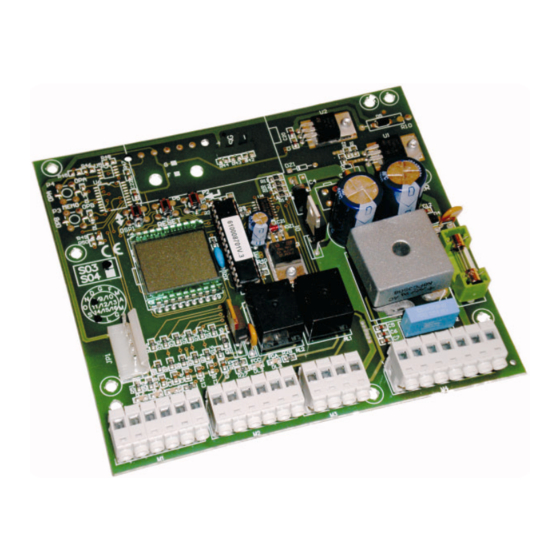
Page 4: Board Lay-Out
4. BOARD LAY-OUT COMPONENTS COMPONENTS Power supply terminal-board Power supply terminal-board Outputs terminal-board Outputs terminal-board CN3 - CN4 Inputs terminal-boards CN3 - CN4 Inputs terminal-boards Receiver coupling Receiver coupling P1 - P2 P1 - P2 Programming push-buttons Programming push-buttons RESET RESET Reset push-button Reset push-button... -
Page 5: Terminal Board Cn2
5.1.3. A CCESSORIES “+24V – -24V” terminals. The accessories power cables should be connected to these terminals. The maximum load of the accessories must not exceed 500 mA. The output of these terminals is DC - observe the power supply polarity of the accessories. 5.1.4. -
Page 6: Terminal Board Cn4
5.4. TERMINAL BOARD CN4 5.4.1. T OTAL OPENING “COM2 – OPEN A” terminals. Normally open contact. Connect, to these terminals, any pulse generator (push-button, key selector, etc...) which by closing a contact, generates a total opening or closing impulse of the gate. The operation of this contact is defined by operating parameter “D”, see paragraph 9. -
Page 7: Installing The Radio Control Receiver Board
No safety device connected No safety device connected A pair of closing photocells A pair of closing photocells A pair of photocells for opening, a pair for closing and A pair of photocells for opening, a pair for closing and A pair of photocells for closing, and a pair for opening A pair of photocells for closing, and a pair for opening a pair for opening and for closing... -
Page 8: Control Leds
7. CONTROL LEDS LEDS Power supply by toroidal transformer Power supply by batteries or no power supply Stop command not activated Stop command activated Closing safety device not engaged Closing safety device engaged Opening safety device not engaged Opening safety device engaged Closing limit switch not engaged Closing limit switch engaged Opening limit switch not engaged... - Page 9 DISPLAY DESCRIPTION Adjustment of sensitivity of the electronic clutch and of motor power. Minimum motor power, more sensitive to obstacle Medium-low motor power, medium-high sensitivity to obstacles Medium-high motor power, medium-low sensitivity to obstacles High motor power, low sensitivity to obstacles Automatic Reclosure: this function enables or disables automatic gate reclosing Disabled Enabled...
-
Page 10: Programming
10. PROGRAMMING During the programming procedure, the control unit memory-stores the mechanical contact points during opening, closing and any pause time before re-closing. Release the gearmotor and position the gate at about halfway of open position. Re-block the gear motor. Power up the control unit and check if value “--”... -
Page 13: How To Secure The Board
14. HOW TO SECURE THE BOARD The outdoor enclosure is designed to house the control unit, the toroidal transformer and any buffer batteries (Optional). To secure the toroidal transformer and the board support, consult the specific instructions. To secure the control board, follow the instructions below: Position the supplied spacers (Ref.
Need help?
Do you have a question about the 724D and is the answer not in the manual?
Questions and answers