Table of Contents

Related Manuals for Avalue Technology EPS-QM67E


Summary of Contents for Avalue Technology EPS-QM67E
- Page 1 EPS-QM67E Fanless Intel® Core™ i7/ i5 Rugged Embedded System with Intel® QM67 Chipset Quick Reference Guide Ed –04 June 2019 Copyright Notice Copyright 2019 Avalue Technology Inc., ALL RIGHTS RESERVED. Part No. E20173828A4R...
- Page 2 Disclaimer Avalue Technology Inc. reserves the right to make changes, without notice, to any product, including circuits and/or software described or contained in this manual in order to improve design and/or performance. Avalue Technology assumes no responsibility or liability for the...
- Page 3 Applications that are described in this manual are for illustration purposes only. Avalue Technology Inc. makes no representation or warranty that such application will be suitable for the specified use without further testing or modification.
-
Page 4: Table Of Contents
EPS-QM67E connector mapping ................. 11 2.2.1 External Serial Port 1 connector (COM1) .................. 11 2.2.2 External Serial Port 2 connector (COM2) .................. 12 Installing Mounting Brackets (EPS-QM67E) ............13 Installing Hard Disk & Memory (EPS-QM67E)............. 15 4 EPS-QM67E Quick Reference Guide... -
Page 5: Getting Started
Place all electronic components in a static-dissipative surface or static-shielded bag when they are not in the chassis. 1.2 Packing List 1x EPS-QM67E Fanless Intel® Sandy Bridge Processor Rugged Embedded System with Intel® QM67 Chipset Other major components include the followings: ... -
Page 6: System Specifications
Operating Temp. -10 ~ 50°C (w/ SSD), Ambient w/ Air Flow; i7-2710QE. Storage Temp. -40 ~ 75°C (-4~167°F) Operating 0%~90% relative humidity, non-condensing Humidity Vibration With SSD: 5Grms, IEC 60068-2-64, Random, 10 ~ 500Hz, 1hr/axis Protection 6 EPS-QM67E Quick Reference Guide... - Page 7 Quick Reference Guide Shock Protection With SSD: 50G, IEC 60068-2-27, Half Sine, 11ms Size (L x W x H) 250mm x 220mm x 60mm Weight 7.7lbs (3.5Kgs) Mounting VESA Compliance Note: Specifications are subject to change without notice. EPS-QM67E Quick Reference Guide...
-
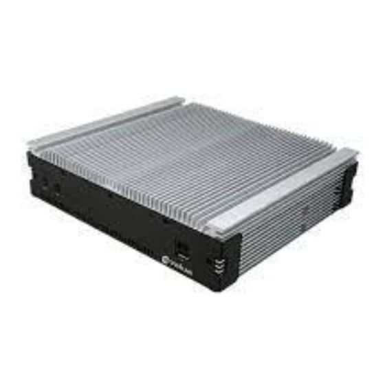
Page 8: System Overview
EPS-QM67E 1.4 System Overview 1.4.1 Front & Top View 8 EPS-QM67E Quick Reference Guide... -
Page 9: Rear View
LAN1 RJ-45 Ethernet 1 LAN2 RJ-45 Ethernet 2 Line-in audio jack LINE IN LINE OUT Line-out audio jack Microphone-in audio jack MIC IN Power System power switch HDMI connector HDMI DVI connector USB connector 1~6 USB1~6 EPS-QM67E Quick Reference Guide... -
Page 10: Hardware Configuration
2. Hardware Configuration Jumper and Connector Setting, Driver and BIOS Installing For advanced information, please refer to: 1- EPI-QM67 Quick Installation Guide or User’s Manual Note: If you need more information, please visit our website: http://www.avalue.com.tw 10 EPS-QM67E Quick Reference Guide... -
Page 11: Eps-Qm67E Connector Mapping
External Serial Port 1 connector (COM1) RS-232* Signal Signal DCD1 DSR1 RXD1 RST1 *Default TXD1 CTS1 DTR1 Note: RS422/RS485 requires OEM BIOS and additional cable. RS-422(Optional) Signal PIN PIN Signal RS-485(Optional) Signal PIN PIN Signal DATA+ DTAT- EPS-QM67E Quick Reference Guide 11... -
Page 12: External Serial Port 2 Connector (Com2)
EPS-QM67E 2.2.2 External Serial Port 2 connector (COM2) Signal Signal DCD1 DSR1 RXD1 RST1 TXD1 CTS1 DTR1 12 EPS-QM67E Quick Reference Guide... -
Page 13: Installing Mounting Brackets (Eps-Qm67E)
Quick Reference Guide 2.2 Installing Mounting Brackets (EPS-QM67E) Step 1. Remove 4 stands from the back of your system to install brackets. Step 2. Locate brackets on both sides, matching the holes on the system Step 3. Insert and fasten 4 screws on each side of the system to secure Mounting brackets... - Page 14 EPS-QM67E Step 4. Installation completed 14 EPS-QM67E Quick Reference Guide...
-
Page 15: Installing Hard Disk & Memory (Eps-Qm67E)
Quick Reference Guide 2.3 Installing Hard Disk & Memory (EPS-QM67E) Step 1. Remove 8 screws from the bottom of your system. Step 2. Remove the chassis cover. Step 1. Slide HDD into its bracket until properly seated. Step 2. Secure HDD by means of 4 screws.
Need help?
Do you have a question about the EPS-QM67E and is the answer not in the manual?
Questions and answers