Table of Contents
Advertisement
Quick Links
Advertisement
Table of Contents

Related Manuals for Avalue Technology HPS-ERSU4A


Summary of Contents for Avalue Technology HPS-ERSU4A
- Page 1 HPS-ERSU4A/ HPS-ERSUTA 19” 4U rackmount workstation, single Intel 4th/5th Xeon SP processor, HPM-ERSUA motherboard, Intel C741 Chipset, 1300W PSU Quick Reference Guide Ed –13 May 2024 Copyright Notice Copyright © 2024 Avalue Technology Inc., ALL RIGHTS RESERVED. Part No. E201744S2A0R...
- Page 2 HPS-ERSU4A/HPS-ERSUTA Document Amendment History Revision Date Comment May 2024 Avalue Initial Release 2 HPS-ERSU4A/HPS-ERSUTA Quick Reference Guide...
- Page 3 For detailed information, please always refer to the electronic user's manual. Copyright Notice © 2024 by Avalue Technology Inc. All rights are reserved. No parts of this manual may be copied, modified, or reproduced in any form or by any means for commercial use without the prior written permission of Avalue Technology Inc.
- Page 4 ㆍDescription of your software (operating system, version, application software, etc.) ㆍA complete description of the problem ㆍThe exact wording of any error messages To receive the latest version of the user’s manual; please visit our Web site at: www.avalue.com 4 HPS-ERSU4A/HPS-ERSUTA Quick Reference Guide...
- Page 5 On the other hand, if the new product defect is resulting from incorrect configuration or erroneous use by the user instead of any problem of the hardware itself, the customer will also be requested to pay for relevant handling fees. HPS-ERSU4A/HPS-ERSUTA Quick Reference Guide...
- Page 6 Lacking detailed statement of fault steps also makes the problem hard to be identified, sometimes resulting in second-time repairs. 6 HPS-ERSU4A/HPS-ERSUTA Quick Reference Guide...
- Page 7 Product has been altered or its label of the serial number has been torn off. • Product functionality issues resulting from improper use by the user, unauthorized dismantle or alteration, unfit operation environment, improper maintenance, accident HPS-ERSU4A/HPS-ERSUTA Quick Reference Guide...
- Page 8 If the customer demands an additional maintenance analysis report, a service fee of various level will be charged depending on the warranty status. In case the analysis result shows that the defect attributes to Avalue’s faulty design or process, the analysis fee will be exempted. 8 HPS-ERSU4A/HPS-ERSUTA Quick Reference Guide...
- Page 9 9. Position the power cord so that people cannot step on it. Do not place anything over the power cord. 10. All cautions and warnings on the equipment should be noted. 11. If the equipment is not used for a long time, disconnect it from the power source to HPS-ERSU4A/HPS-ERSUTA Quick Reference Guide...
- Page 10 The equipment has obvious signs of breakage. 14. CAUTION: Danger of explosion if battery is incorrectly replaced. Replace only with the same or equivalent type recommended by the manufacturer. 15. Equipment intended only for use in a RESTRICTED ACCESS AREA. 10 HPS-ERSU4A/HPS-ERSUTA Quick Reference Guide...
- Page 11 A NOTE provides additional information intended to avoid Note inconveniences during operation. Direct current. Alternating current Stand-by, Power on FCC Certification CE Certification Follow the national requirements for disposal of equipment. Stacking layer limit This side up HPS-ERSU4A/HPS-ERSUTA Quick Reference Guide 11...
- Page 12 HPS-ERSU4A/HPS-ERSUTA Fragile Packaging Beware of water damage, moisture-proof Carton recyclable Handle with care Follow operating instructions of consult instructions for use. 12 HPS-ERSU4A/HPS-ERSUTA Quick Reference Guide...
- Page 13 EXPLOSION ou une fuite de liquide ou de gaz inflammable. - UNE BATTERIE soumise à une pression d'air extrêmement basse pouvant entraî ner une EXPLOSION ou une fuite de liquide ou de gaz inflammable. HPS-ERSU4A/HPS-ERSUTA Quick Reference Guide 13...
-
Page 14: Table Of Contents
1.5.1 HPS-ERSU4A ..........................36 1.5.2 HPS-ERSUTA ..........................37 Operating Principle ....................38 Hardware Configuration ................... 39 HPS-ERSU4A/HPS-ERSUTA connector mapping ..........40 2.1.1 Serial Port connector (COM) ..................... 40 2.1.2 VGA connector (VGA) ........................ 40 Powering On the System ..................41 Connecting to Power Supply ................ - Page 15 In Case of Problems .................... 80 BIOS setup ......................81 4.6.1 Main Menu ..........................81 4.6.1.1 System Language ......................81 4.6.1.2 System Date ........................81 4.6.1.3 System Time ........................81 4.6.2 Advanced Menu ......................... 82 HPS-ERSU4A/HPS-ERSUTA Quick Reference Guide 15...
- Page 16 4.6.4.3.3 Intel VMD technology ...................... 111 4.6.4.3.3.1 Intel VMD for Volume Management Device on Socket 0 ..........112 4.6.4.4 Advanced Power Management Configuration ..............112 4.6.4.4.1 CPU P State Control ....................... 113 4.6.4.4.2 CPU C State Control ....................... 114 16 HPS-ERSU4A/HPS-ERSUTA Quick Reference Guide...
- Page 17 Discard Changes and Reset ................... 124 4.6.8.5 Save Changes ......................... 124 4.6.8.6 Discard Changes ......................124 4.6.8.7 Restore Defaults ......................124 4.6.8.8 Save as User Defaults..................... 124 4.6.8.9 Restore User Defaults ..................... 124 5. Maintenance & Troubleshooting................125 HPS-ERSU4A/HPS-ERSUTA Quick Reference Guide 17...
-
Page 18: Getting Started
Risque d'explosion si la batterie est remplacée par un type incorrect. Jetez les piles usagées selon les instructions 18 HPS-ERSU4A/HPS-ERSUTA Quick Reference Guide... -
Page 19: Packing List
Before installation, please ensure all the items listed in the following table are included in the package. Item Description Q’ty HPS-ERSU4A/HPS-ERSUTA barebone system - HPM-ERSUA motherboard - 1300W PSU Front door key LGA4677 CPU carrier-E1B HPS-ERSU4A/HPS-ERSUTA Quick Reference Guide 19... - Page 20 Step 3: Carefully cut the tape sealing the box. Only cut deep enough to break the tape. Step 4: Open the inside box. Step 5: Lift the panel PC out of the boxes. Step 6: Remove the peripheral parts box from the main box. 20 HPS-ERSU4A/HPS-ERSUTA Quick Reference Guide...
-
Page 21: System Specifications
Slot 5, PCIe 5.0 x16 (Computing GPU – RTX 6000 Ada for L10 system) Slot 6, PCIe 5.0 x4 Slot 7, PCIe 5.0 x16 (Display GPU – T400 for L10 system) (Slot 7 is the slot closest to CPU) HPS-ERSU4A/HPS-ERSUTA Quick Reference Guide 21... - Page 22 Onboard I/O SATA Signal 5 x SATA III Supports up to 6.0 Gb/s 4 x USB 3.1 Gen1 ports (2 x USB 3.1 Gen1 2.0mm pitch Box Header (Pinrex USB Port 52X-8020GB52 or equivalent) Pin definition: 22 HPS-ERSU4A/HPS-ERSUTA Quick Reference Guide...
- Page 23 Notes: LAN2-X ACT LED, “X” means the max number of Ethernet ports. 1 x Avalue HD audio interface (1 x 6x2 2.0mm pitch wafer connector) Signal Signal ACZ_VCC3 ACZ_SYNC ACZ_BITCLK Audio ACZ_SDOUT ACZ_SDIN0 ACZ_SDIN1 ACZ_RST# ACZ_5VSB GND-Chassis Buzzer 1 x onboard Buzzer HPS-ERSU4A/HPS-ERSUTA Quick Reference Guide 23...
- Page 24 1 x Intel X550-AT2 1 x 1G Base-T Ethernet controller Data Rate Per Port 1 x 2.5G Base-T Ethernet controller 1 x Dual 10G Base-T Ethernet controller 1G LAN: 2.5G LAN: LED Indicator 10G LAN: 24 HPS-ERSU4A/HPS-ERSUTA Quick Reference Guide...
- Page 25 Package Vibration Test: 1. PSD: 0.026G²/Hz, 2.16 Grms 2. Non-operation mode 3. Test Frequency: 5-500Hz 4. Test Axis: X, Y and Z axis 5. 30 min. per each axis 6. IEC 60068-2-64 Test: Fh Shock Test Operational: HPS-ERSU4A/HPS-ERSUTA Quick Reference Guide 25...
- Page 26 Windows Server IoT 2019 OS Information Windows Server IoT 2022 Linux: Ubuntu 21.10, 22.04 LTS or later Red Hat Enterprise Linux (RHEL) 8.2 and later In-Box Accessory 2 x Front door key. Accessory 1 x LGA4677 CPU carrier-E1B 26 HPS-ERSU4A/HPS-ERSUTA Quick Reference Guide...
- Page 27 Slot 7, PCIe 5.0 x16 (Display GPU – T400 for L10 system) (Slot 7 is the slot closest to CPU) Storage M.2 (Signal) 1 x M.2 M-Key Slot to support 1 x SATA or 1 x PCIe 3.0 x4 NVMe SSD HPS-ERSU4A/HPS-ERSUTA Quick Reference Guide 27...
- Page 28 SATA Signal 5 x SATA III Supports up to 6.0 Gb/s 4 x USB 3.1 Gen1 ports (2 x USB 3.1 Gen1 2.0mm pitch Box Header (Pinrex 52X-8020GB52 or equivalent) Pin definition : USB Port 28 HPS-ERSU4A/HPS-ERSUTA Quick Reference Guide...
- Page 29 1 x 4 Pin CPU Fan Header (4 Pin PWM) 6 x 4 Pin Chassis Fan Header (4 Pin PWM, 2 for front fans and 4 for rear fans) Display 1 x VGA port (DB15 on edge I/O) Graphic Chipset AST2600 BMC controller HPS-ERSU4A/HPS-ERSUTA Quick Reference Guide 29...
- Page 30 1 x 1G Base-T Ethernet Controller Data Rate Per 1 x 2.5G Base-T Ethernet controller Port 1 x Dual 10G Base-T Ethernet controller 1G LAN: 2.5G LAN: LED Indicator 10G LAN: Power Requirement ACPI Yes, S0 and S5 30 HPS-ERSU4A/HPS-ERSUTA Quick Reference Guide...
- Page 31 4. Test Axis: X, Y and Z axis 5. 30 min. per each axis 6. IEC 60068-2-64 Test: Fh Operational: Shock Test 1. Wave form: Half Sine wave 2. Acceleration Rate: 5.0G for operation mode HPS-ERSU4A/HPS-ERSUTA Quick Reference Guide 31...
- Page 32 HPM-SRSUA/HPM-ERSUA DIMM Sockets DIMM Quantity DIMM1 DIMM2 DIMM3 DIMM4 DIMM5 DIMM6 1 DIMM 1 DIMM 1 DIMM 2 DIMMs 2 DIMMs 4 DIMMs 6 DIMMs Intel 4th & 5th Xeon SP platform DDR5 DIMM configurations Diagram 32 HPS-ERSU4A/HPS-ERSUTA Quick Reference Guide...
-
Page 33: System Overview
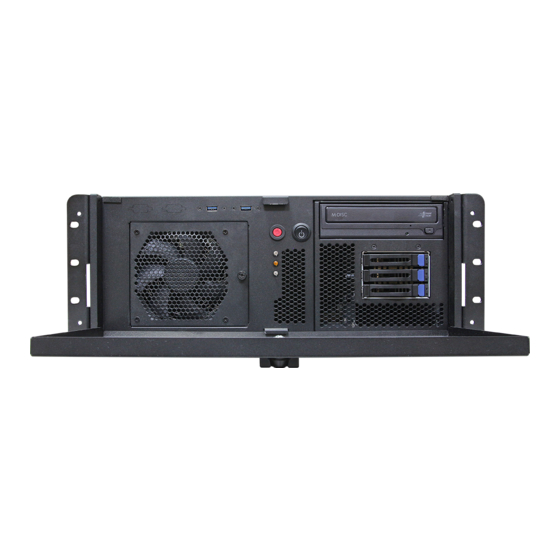
Quick Reference Guide 1.4 System Overview 1.4.1 Front View HPS-ERSU4A HPS-ERSUTA HPS-ERSU4A/HPS-ERSUTA Quick Reference Guide 33... -
Page 34: Rear View
HPS-ERSU4A/HPS-ERSUTA 1.4.2 Rear View HPS-ERSU4A HPS-ERSUTA 34 HPS-ERSU4A/HPS-ERSUTA Quick Reference Guide... - Page 35 Power button Power button USB3.2 6 x USB3.2 Gen1 connector USB2.0 2 x USB2.0 connector Serial port connector D-sub 9-pin, male VGA connector LAN1~4 4 x RJ-45 Ethernet connector MGMT1 MGMT port AC-IN AC power-in connector HPS-ERSU4A/HPS-ERSUTA Quick Reference Guide 35...
-
Page 36: System Dimensions
HPS-ERSU4A/HPS-ERSUTA 1.5 System Dimensions 1.5.1 HPS-ERSU4A (Unit: mm) 36 HPS-ERSU4A/HPS-ERSUTA Quick Reference Guide... -
Page 37: Hps-Ersuta
Quick Reference Guide 1.5.2 HPS-ERSUTA (Unit: mm) HPS-ERSU4A/HPS-ERSUTA Quick Reference Guide 37... -
Page 38: Operating Principle
- Turn ON the system. - Press the power ON/OFF icon firmly to turn power ON/OFF. - The power ON/OFF LED will turn blue to indicate power is on. - Check with the Icon behavior for power status. 38 HPS-ERSU4A/HPS-ERSUTA Quick Reference Guide... -
Page 39: Hardware Configuration
Quick Reference Guide 2. Hardware Configuration Jumper and Connector Setting For advanced information, please refer to: 1- HPM-ERSUA included in this manual. Note: If you need more information, please visit our website: www.avalue.com HPS-ERSU4A/HPS-ERSUTA Quick Reference Guide 39... -
Page 40: Hps-Ersu4A/Hps-Ersuta Connector Mapping
HPS-ERSU4A/HPS-ERSUTA 2.1 HPS-ERSU4A/HPS-ERSUTA connector mapping 2.1.1 Serial Port connector (COM) Signal PIN PIN Signal DCD# DSR# RTS# CTS# DTR# 2.1.2 VGA connector (VGA) Signal PIN Signal PIN Signal GREEN 12 DDCDAT BLUE HSYNC VSYNS DDCCLK 40 HPS-ERSU4A/HPS-ERSUTA Quick Reference Guide... -
Page 41: Powering On The System
The supported power input voltages are: ⚫ Power 1 (DIN connector)): 12 V ~ 28 V ⚫ Power 2 (terminal block)): 12 V ~ 28 V Power Input Connector Power Button HPS-ERSU4A/HPS-ERSUTA Quick Reference Guide 41... -
Page 42: Hpm-Ersua Overviews
HPS-ERSU4A/HPS-ERSUTA 2.4 HPM-ERSUA Overviews 42 HPS-ERSU4A/HPS-ERSUTA Quick Reference Guide... -
Page 43: Hpm-Ersua Jumper & Connector List
PCIE6 PCIe Gen5 x4 PCIe Gen5 x16 (The slot closest to PCIE7 CPU) JFP1 Front Panel connector 10 x 2 wafer, pitch 2.54mm 2 x USB3.1 Gen1 connector USB_LAN1 1 x RJ-45 Ethernet (LAN1 Share HPS-ERSU4A/HPS-ERSUTA Quick Reference Guide 43... - Page 44 CPU PCIE HP SMB connector 5 x 1 header, pitch 2.00mm JAUDIO1 AZALIA connector 6 x 2 wafer, pitch 2.00mm M2(NGFF)1 M.2 M-Key PCIe 3.0 x4 NVMe SSD JCPLD_JTAG1 CPLD JTAG header 5 x 2 header, pitch 2.54mm 44 HPS-ERSU4A/HPS-ERSUTA Quick Reference Guide...
-
Page 45: Hpm-Srsua Jumpers & Connectors Settings
Quick Reference Guide 2.6 HPM-SRSUA Jumpers & Connectors settings 2.6.1 Flash Security Override (JPFLASHSEC) Disable* Enable * Default 2.6.2 ME FW update (JPME1) Normal* ME Force Update * Default HPS-ERSU4A/HPS-ERSUTA Quick Reference Guide 45... -
Page 46: Force Pwron Setting (Jpallpwron1)
HPS-ERSU4A/HPS-ERSUTA 2.6.3 Force PWRON setting (JPALLPWRON1) Normal Operation* Enable Force PWR-ON * Default 2.6.4 Clear CMOS (JPBAT1) Normal Operation* Clear RTC REGISTERS * Default 46 HPS-ERSU4A/HPS-ERSUTA Quick Reference Guide... -
Page 47: Boot Uart5 Setting (Jpboot_Uart5)
Quick Reference Guide 2.6.5 Boot UART5 setting (JPBOOT_UART5) Disable* Enable BOOT FROM UART5 * Default 2.6.6 CPLD JTAG header (JCPLD_JTAG1) Signal PIN PIN Signal JTAG_TCK JTAG_TDO +3.3VSB JTAG_TMS JTAG_TDI HPS-ERSU4A/HPS-ERSUTA Quick Reference Guide 47... -
Page 48: System Fan Connector 1 (Sys_Fan1)
HPS-ERSU4A/HPS-ERSUTA 2.6.7 System fan connector 1 (SYS_FAN1) Signal +12V FAN_TACH1 SYS_PWM1 2.6.8 System fan connector 2 (SYS_FAN2) Signal +12V FAN_TACH2 SYS_PWM2 48 HPS-ERSU4A/HPS-ERSUTA Quick Reference Guide... -
Page 49: System Fan Connector 3 (Sys_Fan3)
Quick Reference Guide 2.6.9 System fan connector 3 (SYS_FAN3) Signal +12V FAN_TACH3 SYS_PWM3 2.6.10 System fan connector 4 (SYS_FAN4) Signal +12V FAN_TACH4 SYS_PWM4 HPS-ERSU4A/HPS-ERSUTA Quick Reference Guide 49... -
Page 50: System Fan Connector 5 (Sys_Fan5)
HPS-ERSU4A/HPS-ERSUTA 2.6.11 System fan connector 5 (SYS_FAN5) Signal +12V FAN_TACH5 SYS_PWM5 2.6.12 System fan connector 6 (SYS_FAN6) Signal +12V FAN_TACH6 SYS_PWM6 50 HPS-ERSU4A/HPS-ERSUTA Quick Reference Guide... -
Page 51: Cpu Fan Connector (Cpu_Fan1)
Quick Reference Guide 2.6.13 CPU fan connector (CPU_FAN1) Signal +12V FAN_TACH0 CPU0_PWM 2.6.14 SPI connector (JSPI1) Signal PIN PIN Signal +3.3VSB SPI_CS# SPI_CLK SPI_MISO SPI_MOSI SPI_IO3 SPI_IO2 HPS-ERSU4A/HPS-ERSUTA Quick Reference Guide 51... -
Page 52: Serial Port 2 Connector (Jcom2)
HPS-ERSU4A/HPS-ERSUTA 2.6.15 Serial port 2 connector (JCOM2) Signal PIN PIN Signal COM_DCD#2 COM_RXD2 COM_TXD2 COM_DTR#2 COM_DSR#2 COM_RTS#2 COM_CTS#2 COM_RI#2 2.6.16 BMC_UART5 debug connector (JCOM5) Signal +3.3VSB UART5_RX UART5_TX 52 HPS-ERSU4A/HPS-ERSUTA Quick Reference Guide... -
Page 53: Serial General Purpose I/O Connector (Jsgpio1)
Quick Reference Guide 2.6.17 Serial General Purpose I/O connector (JSGPIO1) Signal PIN PIN Signal SGPIO_SATA0_DATA0 SGPIO_SATA0_LOAD SGPIO_SATA0_CLOCK 2.6.18 ATX 12V power connector 1 (ATX12V1) Signal Signal +12V +12V +12V +12V HPS-ERSU4A/HPS-ERSUTA Quick Reference Guide 53... -
Page 54: Atx 12V Power Connector 2 (Atx12V2)
HPS-ERSU4A/HPS-ERSUTA 2.6.19 ATX 12V power connector 2 (ATX12V2) Signal Signal +12V +12V +12V +12V 2.6.20 ATX 12V power connector 3 (ATX12V3) Signal Signal +12V +12V +12V +12V 54 HPS-ERSU4A/HPS-ERSUTA Quick Reference Guide... -
Page 55: Atx Power Connector (Atxpwr1)
Quick Reference Guide 2.6.21 ATX power connector (ATXPWR1) Signal PIN PIN Signal +3.3V +3.3V +3.3V -12V PSON# PSU_PWRGD +V5SB +12V +12V +3.3V 2.6.22 Power supply PMBus connector (JPMBUS1) Signal SMB_PSU_SCL SMB_PSU_SDA SMB_PSU_ALERT# HPS-ERSU4A/HPS-ERSUTA Quick Reference Guide 55... -
Page 56: Usb3.1 Gen1 Connector 1 (Jusb1)
USB3_RN5 USB3_RP4 USB3_RP5 USB3_TN4 USB3_TN5 USB3_TP4 USB3_TP5 USB3_PN8 USB3_PN9 USB3_PP8 USB3_PP9 USB_OC1# 2.6.24 USB3.1 Gen1 connector 2 (JUSB2) Signal PIN PIN Signal USB3_RN6 USB3_RN7 USB3_RP6 USB3_RP7 USB3_TN6 USB3_TN7 USB3_TP6 USB3_TP7 USB3_PN11 USB3_PN13 USB3_PP11 USB3_PP13 USB_OC2# 56 HPS-ERSU4A/HPS-ERSUTA Quick Reference Guide... -
Page 57: Front Panel Connector (Jfp1)
Quick Reference Guide 2.6.25 Front Panel connector (JFP1) Signal PIN PIN Signal LAN2-X_LED# LAN2-X_LED_P UID_BUTTON# UID_LED_P SBPWRLED_P UID_LED# LAN1_LED# STATUS_LED# LAN1_LED_P STATUS_LED_P PWRON_BUTTON# RESET_BUTTON# PWR_LED# HDD_LED# +3.3VSB HDD_LED_P 2.6.26 Inlet Thermal Sensor (JINLET_SER1) Signal +3.3VSB SMB_INLET_TEMPSENSOR_SDA SMB_INLET_TEMPSENSOR_SCL HPS-ERSU4A/HPS-ERSUTA Quick Reference Guide 57... -
Page 58: Outlet Thermal Sensor (Joutlet_Ser1)
HPS-ERSU4A/HPS-ERSUTA 2.6.27 Outlet Thermal Sensor (JOUTLET_SER1) Signal +3.3VSB SMB_OUTLET_TEMPSENSOR_SDA SMB_OUTLET_TEMPSENSOR_SCL 2.6.28 HDD Backplane thermal Sensor (JHDD_SER1) Signal +3.3VSB SMB_HDBP_TEMPSENSOR_SDA SMB_HDBP_TEMPSENSOR_SCL SSD_LED_N 58 HPS-ERSU4A/HPS-ERSUTA Quick Reference Guide... -
Page 59: Case Open Connector (Jcase_Open1)
Quick Reference Guide 2.6.29 CASE OPEN connector (JCASE_OPEN1) Signal CHASSIS_INTRUSION 2.6.30 SATA RAID KEY connector (JRAID_KEY1) Signal PU_KEY_CONN PCH_SATA_RAIDKEY HPS-ERSU4A/HPS-ERSUTA Quick Reference Guide 59... -
Page 60: Cpu Pcie Hp Smb Connector (Jpehpsmb1)
HPS-ERSU4A/HPS-ERSUTA 2.6.31 CPU PCIE HP SMB connector (JPEHPSMB1) Signal SMB_CPUHP_SCL SMB_CPUHP_SDA SMB_CPUHP_ALERT# 2.6.32 ESPI connector (JESPI1) Signal PIN PIN Signal ESPI_D0 +3.3VSB ESPI_D1 PLTRST# ESPI_D2 ESPI_CS# ESPI_D3 ESPI_CLK ESPI_RESET# ESPI_ALERT# 60 HPS-ERSU4A/HPS-ERSUTA Quick Reference Guide... -
Page 61: Azalia Connector (Jaudio1)
Quick Reference Guide 2.6.33 AZALIA connector (JAUDIO1) Signal PIN PIN Signal +3.3V AUD_AZA_SYNC AUD_AZA_BCLK AUD_AZA_SDO AUD_AZA_SDI0 AUD_AZA_SDI1 AUD_AZA_RST_N +5VSB 2.6.34 SMBUS VR connector (JVR_PRG1) Signal SMB_VR_SDA SMB_VR_SCL HPS-ERSU4A/HPS-ERSUTA Quick Reference Guide 61... -
Page 62: Processor Installation Sop
Please ensure the carrier model on the CPU is consistent with the carrier silkscreen. Install the CPU on the carrier and align the triangle marks (Pin 1). Look at the below red frame, please make sure the lever is pressed down. 62 HPS-ERSU4A/HPS-ERSUTA Quick Reference Guide... - Page 63 HPM-SRSUA/HPM-ERSUA and Avalue Cooler BCC-FAN-467-01R.) Note: The Thermal grease must be pre-applied on the heatsink before installation. Note: Please ensure the direction of the fan before installing the CPU kit on the Cooler module. HPS-ERSU4A/HPS-ERSUTA Quick Reference Guide 63...
- Page 64 Hold the Cooler module with the CPU and align the holes with the CPU socket. Press the Cooler module down to the CPU socket until it snaps into place. c. Press down the fixing tenons on the four sides to fixate. (Figure B) 64 HPS-ERSU4A/HPS-ERSUTA Quick Reference Guide...
- Page 65 ★ The cooler module with CPU pin1 must be aligned with the CPU socket pin1 mark, and the direction cannot be changed at will, or it may cause the CPU to damage after pressing. CPU Socket Cooler Module with CPU Upside down Pin1 Pin 1 ▲Figure A HPS-ERSU4A/HPS-ERSUTA Quick Reference Guide 65...
- Page 66 Install the cooling fan and holder on the cooler module and tighten two locking screws (T30) on the top of the fan holder. Note: The 4U cooler’s fan for Xeon SP single socket is facing the opposite side of Edge I/O. 66 HPS-ERSU4A/HPS-ERSUTA Quick Reference Guide...
- Page 67 Quick Reference Guide Connect the cooling fan connector to the fan header labeled for the CPU on the motherboard. HPS-ERSU4A/HPS-ERSUTA Quick Reference Guide 67...
-
Page 68: Drivers Installation
HID touch digitizer built-in driver in Windows 7 or later. Note: Installation procedures and screen shots in this section are for your reference and may not be exactly the same as shown on your screen. 68 HPS-ERSU4A/HPS-ERSUTA Quick Reference Guide... -
Page 69: Install Chipset Driver
Windows 11 operation system. If the warning message appears while the installation process, click Continue to go on. Step 3. Click Install. Step1. Click Next. Step 4. Setup completed. Step 2. Click Accept. HPS-ERSU4A/HPS-ERSUTA Quick Reference Guide 69... -
Page 70: Install Vga Driver
Windows 11 operation system. Step 3. Click Next. Step 1. Click Next to continue installation. Step 4. Click Next. Step 2. Click Next. Step 5. Click Install. 70 HPS-ERSU4A/HPS-ERSUTA Quick Reference Guide... - Page 71 Quick Reference Guide Step 6. Click Finish to complete setup. HPS-ERSU4A/HPS-ERSUTA Quick Reference Guide 71...
-
Page 72: Install Audio Driver
All drivers can be found on the Avalue Official Website: www.avalue.com. Note: The installation procedures and screen shots in this section are based on Windows 11 operation system. Step 1. Click Yes to continue installation. Step 2. Setup completed. 72 HPS-ERSU4A/HPS-ERSUTA Quick Reference Guide... -
Page 73: Install Ethernet Driver
All drivers can be found on the Avalue Official Website: www.avalue.com. Note: The installation procedures and screen shots in this section are based on Windows 11 operation system. Step 1. Click OK to continue installation. Step 2. Setup completed. HPS-ERSU4A/HPS-ERSUTA Quick Reference Guide 73... -
Page 74: Install Quickassist Technology Driver
Windows 11 operation system. Step 3. Click Next. Step 1. Click Next to continue installation. Step 4. Click Install. Step 2. Click Next. Step 5. Click Finish to complete setup. 74 HPS-ERSU4A/HPS-ERSUTA Quick Reference Guide... -
Page 75: Install Vroc Driver
Note: The installation procedures and screen shots in this section are based on Windows 11 operation system. Step 3. Click Accept. Step 1. Click Install to continue installation. Step 4. Click Next. Step 2. Click Next. Step 5. Click Install. HPS-ERSU4A/HPS-ERSUTA Quick Reference Guide 75... - Page 76 HPS-ERSU4A/HPS-ERSUTA Step 6. Setup completed. 76 HPS-ERSU4A/HPS-ERSUTA Quick Reference Guide...
-
Page 77: Bios Setup
Quick Reference Guide 4.BIOS Setup HPS-ERSU4A/HPS-ERSUTA Quick Reference Guide 77... -
Page 78: Introduction
If the message disappears before you respond and you still wish to enter Setup, restart the system to try again by turning it OFF then ON or pressing the "RESET" button on the system case. You may also restart by simultaneously pressing <Ctrl>, <Alt>, and <Delete> keys. 78 HPS-ERSU4A/HPS-ERSUTA Quick Reference Guide... -
Page 79: Using Setup
Note: Some of the navigation keys differ from one screen to another. • To Display a Sub Menu Use the arrow keys to move the cursor to the sub menu you want. Then press <Enter>. A “➢” pointer marks all sub menus. HPS-ERSU4A/HPS-ERSUTA Quick Reference Guide 79... -
Page 80: Getting Help
BIOS Vendor and your systems manufacturer to provide the absolute maximum performance and reliability. Even a seemingly small change to the chipset setup has the potential for causing you to use the override. 80 HPS-ERSU4A/HPS-ERSUTA Quick Reference Guide... -
Page 81: Bios Setup
Note: The BIOS setup screens shown in this chapter are for reference purposes only, and may not exactly match what you see on your screen. Visit the Avalue website (www.avalue.com) to download the latest product and BIOS information. HPS-ERSU4A/HPS-ERSUTA Quick Reference Guide 81... -
Page 82: Advanced Menu
4.6.2.1 Trusted Computing Item Options Description Enables or Disables BIOS support for security device. Disable, Security Device Support O.S. will not show Security Device. TCG EFI protocol Enable[Default] and INT1A interface will not be available. 82 HPS-ERSU4A/HPS-ERSUTA Quick Reference Guide... -
Page 83: Acpi Settings
Enable ACPI Auto Disabled[Default] Enables or Disables BIOS ACPI Auto Configuration. Configuration Enabled Enables or Disables System ability to Hibernate Disabled Enable Hibernation (OS/S4 Sleep State). This option may not be effective Enabled[Default] with some operating systems. HPS-ERSU4A/HPS-ERSUTA Quick Reference Guide 83... -
Page 84: Ast2600 Super Io Configuration
Set Parameters of Serial Port 1 (COMA). Serial Port 2 Configuration Set Parameters of Serial Port 2 (COMB). 4.6.2.3.1 Serial Port 1 Configuration Item Option Description Enabled[Default], Serial Port Enable or Disable Serial Port (COM). Disabled 84 HPS-ERSU4A/HPS-ERSUTA Quick Reference Guide... -
Page 85: Serial Port 2 Configuration
4.6.2.3.2 Serial Port 2 Configuration Item Option Description Enabled[Default], Serial Port Enable or Disable Serial Port (COM). Disabled 4.6.2.4 Serial Port Console Redirection Item Options Description Disabled[Default], Console Redirection Console Redirection Enable or Disable. Enabled HPS-ERSU4A/HPS-ERSUTA Quick Reference Guide 85... -
Page 86: Option Rom Dispatch Policy
@ s0|Bx0 |Dx11 |Fx5 Onboard Device has: UEFI [X] Enabled[Default], Legacy [X] Onboard Display Controller Disabled Embedded ROM(s). VIDx1A03; DIDx2000 @ s0|BxA |Dx0 |Fx0 Onboard Device has: Enabled[Default], UEFI [X] Onboard Network Controller Disabled Legacy [X] Embedded ROM(s). 86 HPS-ERSU4A/HPS-ERSUTA Quick Reference Guide... -
Page 87: Usb Configuration
XHCI driver. Disabled Enable/Disable USB Mass Storage Driver USB Mass Storage Driver Support Enabled[Default], Support. Disabled Enables I/O port 60h/64h emulation support. Port 60/64 Emulation Enabled[Default], This should be enabled for the complete USB HPS-ERSU4A/HPS-ERSUTA Quick Reference Guide 87... -
Page 88: Network Stack Configuration
Optical drives are emulated as ‘CDROM’, drives with no media will be Hard Disk CD-ROM emulated according to a drive type. 4.6.2.7 Network Stack Configuration Item Options Description Enabled Network Stack Enable/Disable UEFI Network Stack. Disabled[Default] 88 HPS-ERSU4A/HPS-ERSUTA Quick Reference Guide... -
Page 89: Nvme Configuration
Quick Reference Guide 4.6.2.8 NVMe Configuration 4.6.3 Platform Config HPS-ERSU4A/HPS-ERSUTA Quick Reference Guide 89... -
Page 90: Pch-Io Configuration
SAI is set. Flash Protection Range Disabled[Default] Enable Flash Protection Range Registers. Registers(FRRR) Enabled Enable/Disable setting SPD Write Disable Disabled SPD Write Disable bit. For sucurity recommendations, SPD Enabled[Default] write disable bit must be set. 90 HPS-ERSU4A/HPS-ERSUTA Quick Reference Guide... -
Page 91: Pci Express Configuration
Quick Reference Guide 4.6.3.1.1 PCI Express Configuration Item Option Description Disabled[Default] PCI Express Port8xh Decode Port8xh Decode Enabled Enable/Disable. Disabled[Default] Enable when using Compliance Load Compliance Test Mode Enabled Board. 4.6.3.1.1.1 PCI Express Root Port 5(M.2 Key-M) HPS-ERSU4A/HPS-ERSUTA Quick Reference Guide 91... -
Page 92: Pci Express Root Port 9(Bmc.2600)
PCI Express Root Port 9(BMC. Enabled[Default], Control the PCI Express Root Port. 2600) Disabled Disabled[Default], PCI Express Active State Power ASPM Management settings. Disabled[Default] L1.1 L1 Substates PCI Express L1 Substates settings. L1.2 L1.1 & L1.2 92 HPS-ERSU4A/HPS-ERSUTA Quick Reference Guide... -
Page 93: Pci Express Root Port 10(Lan 210/211)
PCI Express Active State Power ASPM Management settings. Disabled[Default] L1.1 L1 Substates PCI Express L1 Substates settings. L1.2 L1.1 & L1.2 Enabled[Default], Enable/Disable Precision Time Disabled Measurement. Auto[Default] Gen1 PCIe Speed Configure PCIe Speed. Gen2 Gen3 HPS-ERSU4A/HPS-ERSUTA Quick Reference Guide 93... -
Page 94: Pci Express Root Port 11(Lan 225/226)
PCI Express Active State Power ASPM Management settings. Disabled[Default] L1.1 L1 Substates PCI Express L1 Substates settings. L1.2 L1.1 & L1.2 Enabled[Default], Enable/Disable Precision Time Disabled Measurement. Auto[Default] Gen1 PCIe Speed Configure PCIe Speed. Gen2 Gen3 94 HPS-ERSU4A/HPS-ERSUTA Quick Reference Guide... -
Page 95: Sata And Rst Configuration
4.6.3.1.2.1 Controller 2 SATA And RST Configuration Item Options Description Enabled[Default] SATA Configuration SATA test settings. Disabled, AHCI[Default], SATA Mode Selection Determines how SATA controller(s) operate. RAID Enabled SATA Test Mode Test Mode Enable/Disable (Loop Back). Disabled[Default] HPS-ERSU4A/HPS-ERSUTA Quick Reference Guide 95... - Page 96 Otherwise all drives spin up at boot. Hard Disk Drive[Default] Identify the SATA port is connected to Solid SATA Device Type Solid State Drive State Drive or Hard Disk Drive. 96 HPS-ERSU4A/HPS-ERSUTA Quick Reference Guide...
-
Page 97: Controller 3 Sata And Rst Configuration
If enabled for any of ports Staggerred Spin Up Disabled[Default] will be performed and only the drives which Spin Up Device Enabled have this option enabled will spin up at boot. Otherwise all drives spin up at boot. HPS-ERSU4A/HPS-ERSUTA Quick Reference Guide 97... - Page 98 Otherwise all drives spin up at boot. Hard Disk Drive[Default] Identify the SATA port is connected to Solid SATA Device Type Solid State Drive State Drive or Hard Disk Drive. 98 HPS-ERSU4A/HPS-ERSUTA Quick Reference Guide...
-
Page 99: Software Feature Mask Configuration For Controller 2
OS is enabled. If enabled, indicates that the LED/SGPIO Disabled, LED Locate hardware is attached and ping to locate Enabled[Default] feature is enabled on the OS. 4.6.3.1.2.4 Software Feature Mask Configuration for Controller 3 HPS-ERSU4A/HPS-ERSUTA Quick Reference Guide 99... -
Page 100: Usb Configuration
USB Overcurrent Lock used. Enabling this will make xHCI controller Enabled[Default] consume the Overcurrent mapping data. Selectively Enable/Disable the corresponding USB Disabled[Default] USB Port Disable Override port from reporting a Device Connection to the Select Per-Pin controller. 100 HPS-ERSU4A/HPS-ERSUTA Quick Reference Guide... -
Page 101: Hd Audio Configuration
Quick Reference Guide 4.6.3.1.4 HD Audio Configuration Item Options Description Control Detection of the HD-Audio device. Disabled, HD Audio Disabled=HDA will be unconditionally disabled Enabled[Default] Enabled=HDA will be unconditionally enabled. 4.6.3.2 Server ME Configuration HPS-ERSU4A/HPS-ERSUTA Quick Reference Guide 101... -
Page 102: Socket Config
Provide the 8000h value if the altitude is unknown. MCTP bus owner location on PCIe: [15:8] bus, [7:3] device, MCTP Bus Owner [2:0] function. If all zeros sending bus owner is disabled. 4.6.4 Socket Config 4.6.4.1 Processor Configuration 102 HPS-ERSU4A/HPS-ERSUTA Quick Reference Guide... -
Page 103: Per-Socket Configuration
Quick Reference Guide Item Option Description Enable/disable extended APIC support. Disable Extended APIC Note: When enabled, VT-d_Interrupt Enable[Default] Remapping will be automatically enabled. 4.6.4.1.1 Per-Socket Configuration 4.6.4.1.1.1 CPU Socket 0 Configuration HPS-ERSU4A/HPS-ERSUTA Quick Reference Guide 103... -
Page 104: Memory Configuration
3600 MT/s. If Enforce POR is disabled, user will 4000 Memory Frequency be able to run at higher frequencies than 4400 the memory suppot (limited by processor 4800 support). Do not select Reserved. 5200 5600 104 HPS-ERSU4A/HPS-ERSUTA Quick Reference Guide... -
Page 105: Memory Topology
Quick Reference Guide 4.6.4.2.1 Memory Topology 4.6.4.3 IIO Configuration HPS-ERSU4A/HPS-ERSUTA Quick Reference Guide 105... -
Page 106: Socket0 Configuration
Auto Selects PCIe port Bifurcation for selected x4x4x4x4 IOU1 PCIe Slot3 x16 x4x4x_x8 slot(s) Port Format: xDxCxBxA The port x_x8x4x4 can further be x2x2. x_x8x_x8 106 HPS-ERSU4A/HPS-ERSUTA Quick Reference Guide... - Page 107 Auto x4x4x4x4 x4x4x_x8 x_x8x4x4 Selects PCIe port Bifurcation for selected x_x8x_x8 IOU3 PCIe Slot7 x16 x_x_x_x16[Default] slot(s) Port Format: xDxCxBxA The port x2x2x4x_x8 can further be x2x2. x4x2x2x_x8 x_x8x2x2x4 x2x2x4x4x4 x4x2x2x4x4 HPS-ERSU4A/HPS-ERSUTA Quick Reference Guide 107...
- Page 108 Select PCIe Subsystem Mode for selected slot(s) Gen4: Gen4 controller Gen5 Port 2 Subsystem Mode only Gen5: Gen5 with or without mix Protocol Auto Negotiation[Default] mode Auto: Auto select Force CXL: There is no training discovery, the attached 108 HPS-ERSU4A/HPS-ERSUTA Quick Reference Guide...
- Page 109 Applies to root ports only. Enabled Sck0 RP NonFatal No[Default] Uncorrectable Err interrupt on a non-fatal error. Applies to root ports only. Enabled Sck0 RP Fatal No[Default] Uncorrectable Err MSI/INTx interrupt on fatal errors. HPS-ERSU4A/HPS-ERSUTA Quick Reference Guide 109...
-
Page 110: Port Dmi
Gen 5 (32 GT/s) -6.0 dB[Default] De-Emphais control (LNKCON2[6]) for this PCIe PCI-E Port DeEmphasis -3.5 dB port. Disabled[Default] This option can disable ASPM support in a PCIe PCI-E ASPM Support root port. ‘Auto’ keeps hardware default. Auto 110 HPS-ERSU4A/HPS-ERSUTA Quick Reference Guide... -
Page 111: Intel Vt For Directed I/O (Vt-D)
Eneble/Disable Intel Virtualization Technology for Directed I/O (VT-d) by reporting the I/O device Enable[Default] Intel VT for Directed I/O Disable assignment to VMM through DMAR ACPI Tables. To disable VT-d, X2APIC must also be disabled. 4.6.4.3.3 Intel VMD technology HPS-ERSU4A/HPS-ERSUTA Quick Reference Guide 111... -
Page 112: Intel Vmd For Volume Management Device On Socket 0
HPS-ERSU4A/HPS-ERSUTA 4.6.4.3.3.1 Intel VMD for Volume Management Device on Socket 0 Item Option Description Disable[Default] Enable/Disable VMD Enable/Disable VMD in this Stack. Enable 4.6.4.4 Advanced Power Management Configuration 112 HPS-ERSU4A/HPS-ERSUTA Quick Reference Guide... -
Page 113: Cpu P State Control
Set by Intel Node Manager Enable[Default] Energy Efficient Turbo Disable, MSR Energy Efficient Turbo Disable 0x1FC[19]. Disable Enable/Disable processor Turbo Mode Turbo Mode Enable[Default] (requires EMTTM enabled too). Disable[Default] Enable/Disable CPU Flex Ratio CPU Flex Ratio Override Enable Programming. HPS-ERSU4A/HPS-ERSUTA Quick Reference Guide 113... -
Page 114: Cpu C State Control
Disable effect after reboot. Will be enforced to Enhanced Halt State (C1E) Enable[Default] enable when Optimized Power Mode is enabled. ACPI C2[Default] Report CC3/CC6 to OS ACPI C2 or ACPI OS ACPI Cx ACPI C3 114 HPS-ERSU4A/HPS-ERSUTA Quick Reference Guide... -
Page 115: Server Mgmt
Options Description Enabled[Default] BMC Support Enable/Disable interfaces to communicate with BMC. Disabled Kcs Interface[Default] Ssif Interface Ipmb Interface IPMI Interface Type Type of Interface to communicate BMC from HOST. Usb Interface Oem1 Interface Oem2 Interface HPS-ERSU4A/HPS-ERSUTA Quick Reference Guide 115... -
Page 116: System Event Log
Reset not required as selected Power policy will Power Restore Unspecified[Default] be set in BMC when policy is saved. BMC Warm Reset Press <Enter> to do Warm Reset BMC. 4.6.5.1 System Event Log 116 HPS-ERSU4A/HPS-ERSUTA Quick Reference Guide... -
Page 117: Bmc Self Test Log
Bmc self test log Item Option Description Yes, On every reset[Default] Erase Log Erase Log Options. Clear Log[Default] When log is full Select the action to be taken when log is full. Do not log any more HPS-ERSU4A/HPS-ERSUTA Quick Reference Guide 117... -
Page 118: Bmc Network Configuration
Description Unspecified[Default] Select configure LAN channel parameters Configuration Address Static statically or dynamically(by BIOS or BMC). source DynamicBmcDhcp Unspecified option will not modify any BMC DynamicBmcNonDhcp network parameters during BIOS phase. 4.6.5.4 BMC User Settings 118 HPS-ERSU4A/HPS-ERSUTA Quick Reference Guide... -
Page 119: Bmc Add User Details
Quick Reference Guide 4.6.5.4.1 BMC Add User Details Item Description User Name Enter BMC User Name. 4.6.5.4.2 BMC Delete User Details Item Description User Name Enter BMC User Name. HPS-ERSU4A/HPS-ERSUTA Quick Reference Guide 119... -
Page 120: Bmc Change User Settings
HPS-ERSU4A/HPS-ERSUTA 4.6.5.4.3 BMC Change User Settings Item Description User Name Enter BMC User Name. 4.6.6 Security ⚫ Administrator Password Set setup Administrator Password ⚫ User Password Set User Password 120 HPS-ERSU4A/HPS-ERSUTA Quick Reference Guide... -
Page 121: Secure Boot
The mode chagne requires platform reset. Secure Boot mode options: Standard or Custom. In Standard[Default] Custom mode, Secure Boot Policy variables can be Secure Boot Mode Custom configured by a physically present user without full authentication. 4.6.7 Boot HPS-ERSU4A/HPS-ERSUTA Quick Reference Guide 121... - Page 122 Set the system boot order. USB Device Network Disabled Hard Disk NVME CD/DVD[Default] Boot Option #3 Set the system boot order. USB Device Network Disabled Hard Disk Boot Option #4 Set the system boot order. NVME 122 HPS-ERSU4A/HPS-ERSUTA Quick Reference Guide...
-
Page 123: Save And Exit
Optimized Boot will disable Csm support and Disabled[Default] disable connecting Network devices to decrease Optimized Boot Enabled boot time. While disabling Optimized Boot, make sure to restore Csm Support option to previous value before enabling Optimized Boot. 4.6.8 Save and exit HPS-ERSU4A/HPS-ERSUTA Quick Reference Guide 123... -
Page 124: Save Changes And Exit
This option saves a copy of the current BIOS settings as the User Defaults. This option is useful for preserving custom BIOS setup configurations. 4.6.8.9 Restore User Defaults This option restores all BIOS settings to the user defaults. This option is useful for restoring previously preserved custom BIOS setup configurations. 124 HPS-ERSU4A/HPS-ERSUTA Quick Reference Guide... -
Page 125: Maintenance & Troubleshooting
System Maintenance Introduction If the components of the product fail they must be replaced. Please contact the system reseller or vendor to purchase the replacement parts. Please follow the safety precautions outlined in the sections that follow HPS-ERSU4A/HPS-ERSUTA Quick Reference Guide 125... - Page 126 Drop the device against a hard surface. ⚫ Strike or exert excessive force onto the LCD panel. ⚫ Touch any of the LCD panels with a sharp object. ⚫ In a site where the ambient temperature exceeds the rated temperature. 126 HPS-ERSU4A/HPS-ERSUTA Quick Reference Guide...
- Page 127 This reduces the possibility of ESD damage. ⚫ Only handle the edges of the electrical component. When handling the electrical component, hold the electrical component by its edges. Please ensure the following safety precautions are adhered to at all times. HPS-ERSU4A/HPS-ERSUTA Quick Reference Guide 127...
- Page 128 Never drop any objects or liquids through the openings of the device. ⚫ Be cautious of any possible allergic reactions to solvents or chemicals used when cleaning the device. ⚫ Avoid eating, drinking and smoking within vicinity of the device. 128 HPS-ERSU4A/HPS-ERSUTA Quick Reference Guide...
- Page 129 Cotton swabs: Cotton swaps moistened with rubbing alcohol or water are excellent tools for wiping hard to reach areas. ⚫ Foam swabs: Whenever possible, it is best to use lint free swabs such as foam swabs for cleaning. HPS-ERSU4A/HPS-ERSUTA Quick Reference Guide 129...
- Page 130 No Console Input Devices are found Flash update is failed Typically for development use. The beep code is generated when platform cannot be reset because reset protocol is not available. Platform PCI resource requirements cannot be met 130 HPS-ERSU4A/HPS-ERSUTA Quick Reference Guide...
Need help?
Do you have a question about the HPS-ERSU4A and is the answer not in the manual?
Questions and answers